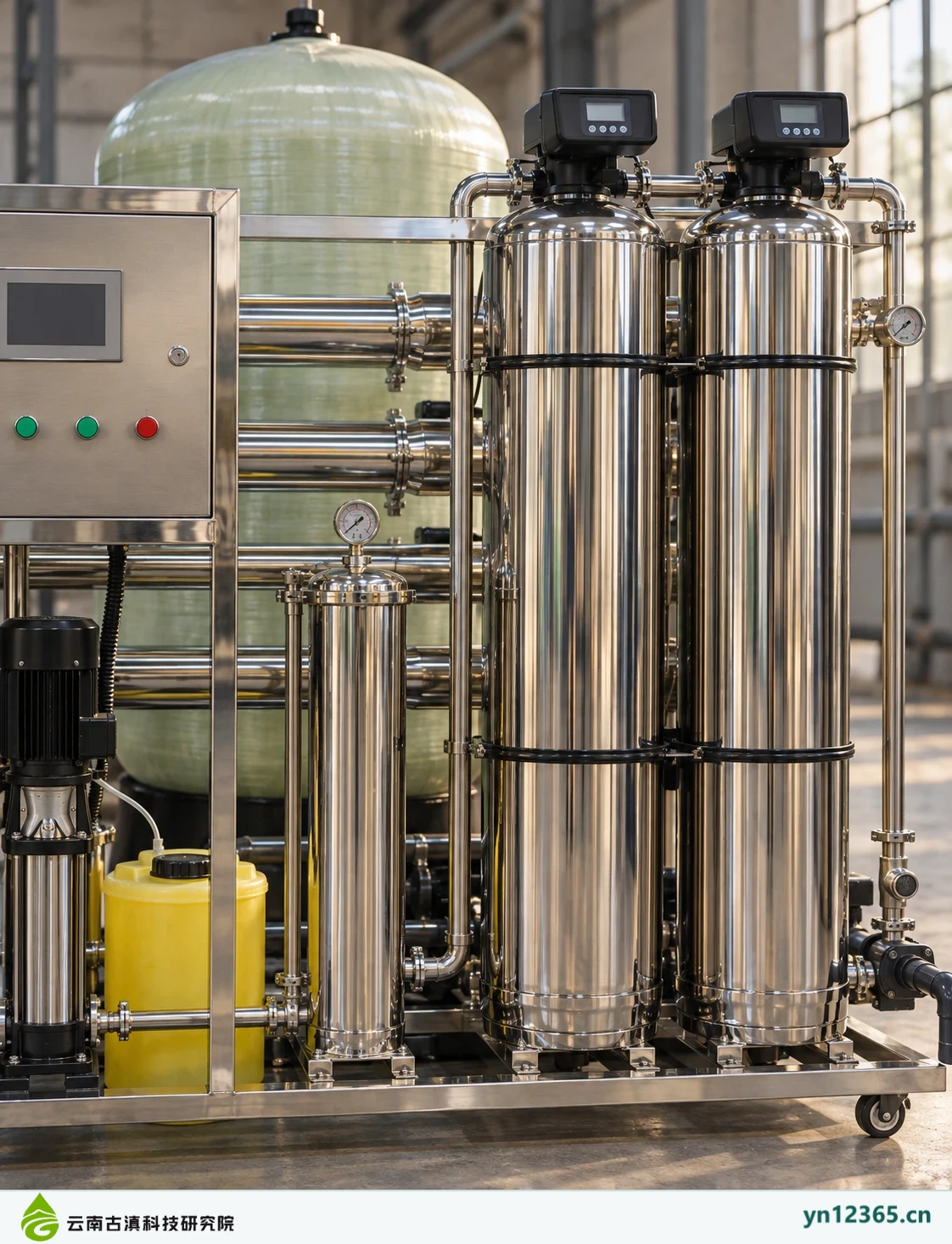
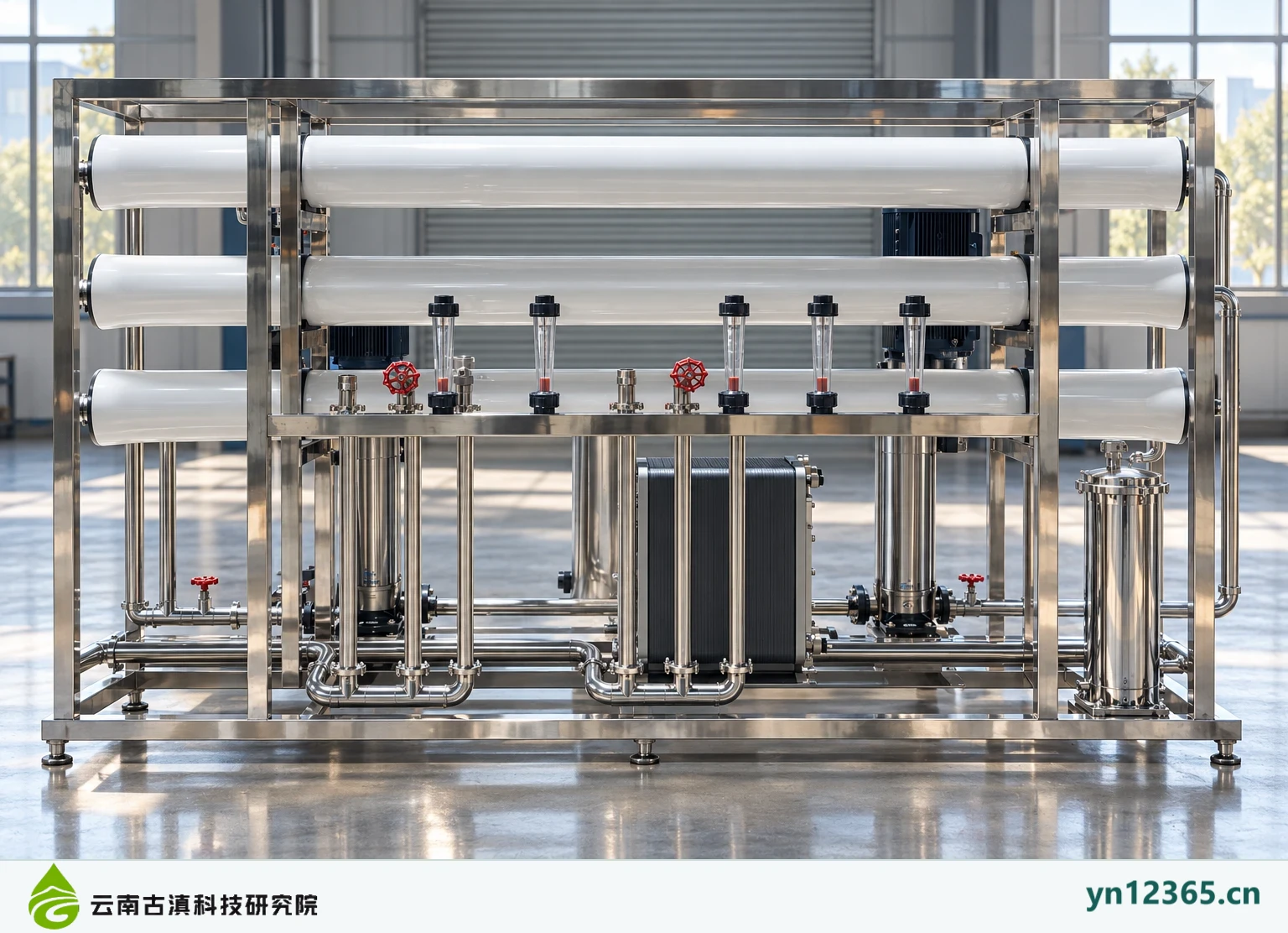
RO and EDI equipment gallery: how to examine membrane racks, controls, and connections

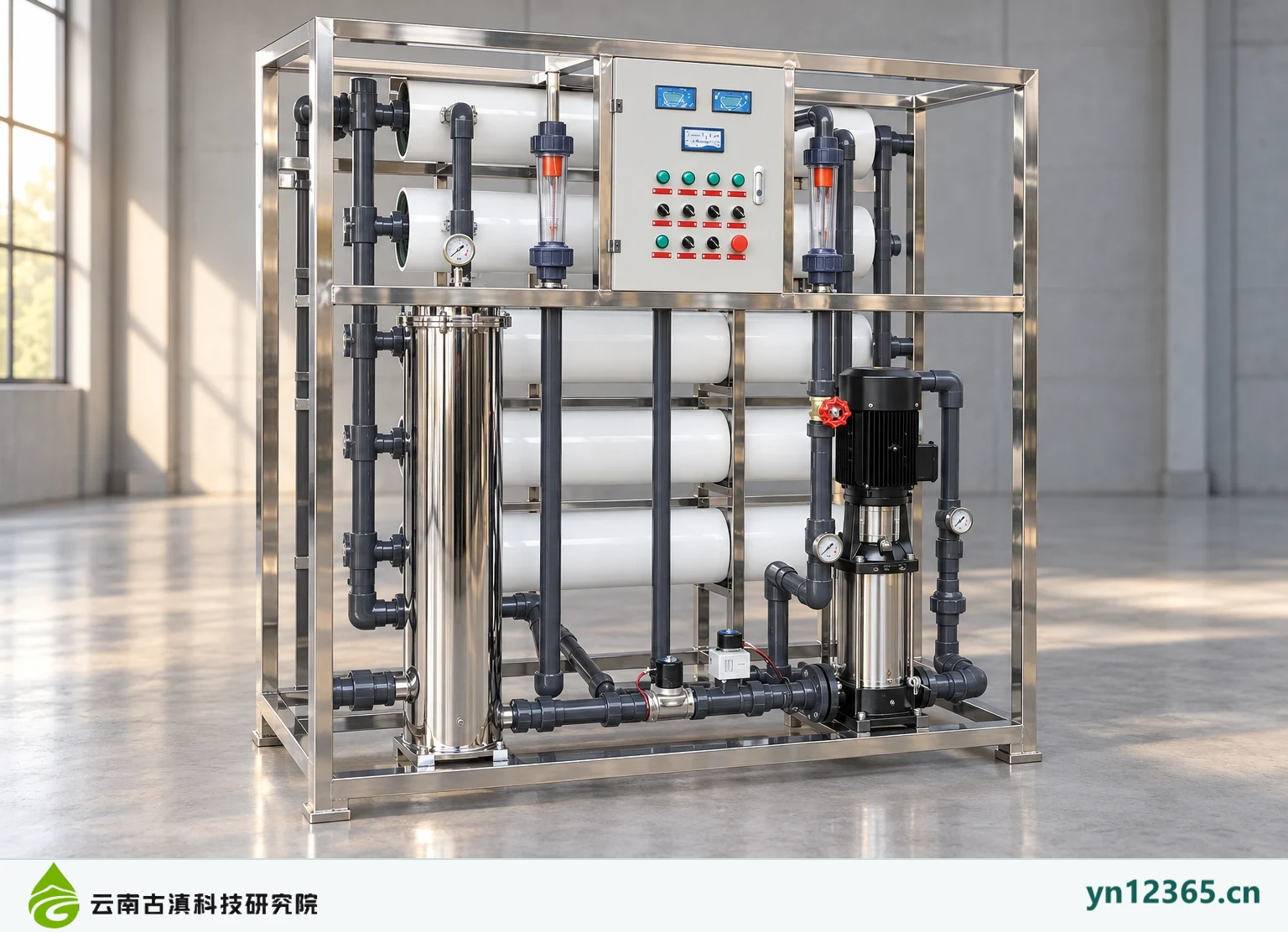
This gallery brings together exterior and detail illustrations of RO- and EDI-related equipment to discuss frames, membrane housings, instruments, controls, and service clearance. Image group names describe the material's theme. They do not prove that specific elements are installed inside the equipment, and the images are not customer project photographs.

RO and EDI equipment gallery: how to examine membrane racks, controls, and connections

Category gallery · All images are AI-assisted illustrations, not actual customer project photographs

This gallery brings together exterior and detail illustrations of RO- and EDI-related equipment to discuss frames, membrane housings, instruments, controls, and service clearance. Image group names describe the material's theme. They do not prove that specific elements are installed inside the equipment, and the images are not customer project photographs.

Observe complete equipment and components separately

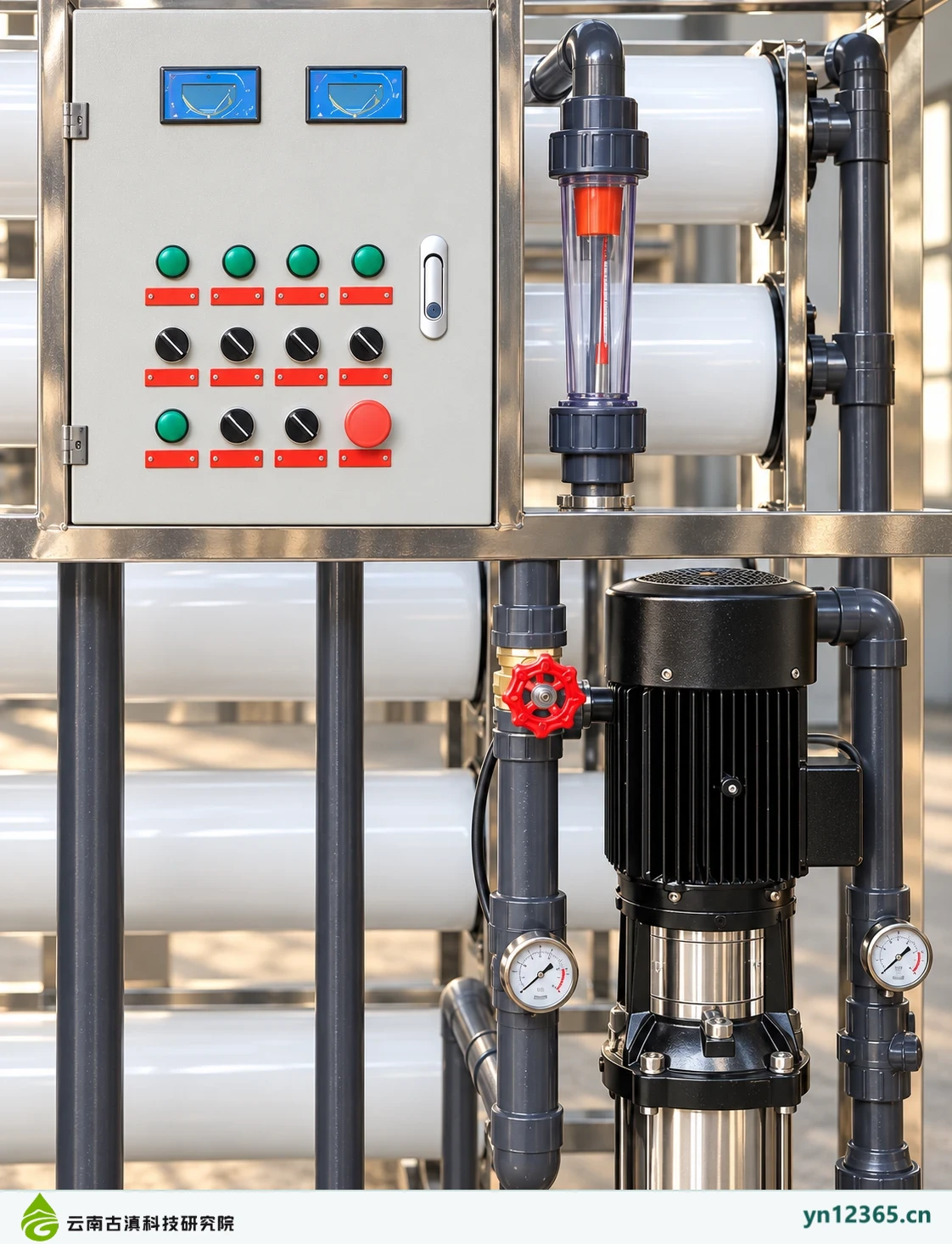
First examine relative layouts in complete equipment illustrations, then view controls, membrane frames, and other details. Positions and quantities help raise questions, but actual membrane models, pumps, valves, connections, electrical systems, and allowable operating conditions require corresponding documentation. Pictured instrument interfaces and readings cannot serve as an operating baseline.

Turn visual questions into documentation questions

For an inquiry, state the installation connections, service clearance, and downstream requirements you wish to check. The gallery supports exterior discussions. Consult model documentation separately for construction dimensions and handling weight. Assess whether EDI and other supporting equipment are suitable against complete treatment objectives and system design, beyond appearance alone.

Equipment and scene illustrations

Click an image to view it at full size. Images are for discussing layouts and requirements only. Confirm models, parameters, and delivery against corresponding documentation.
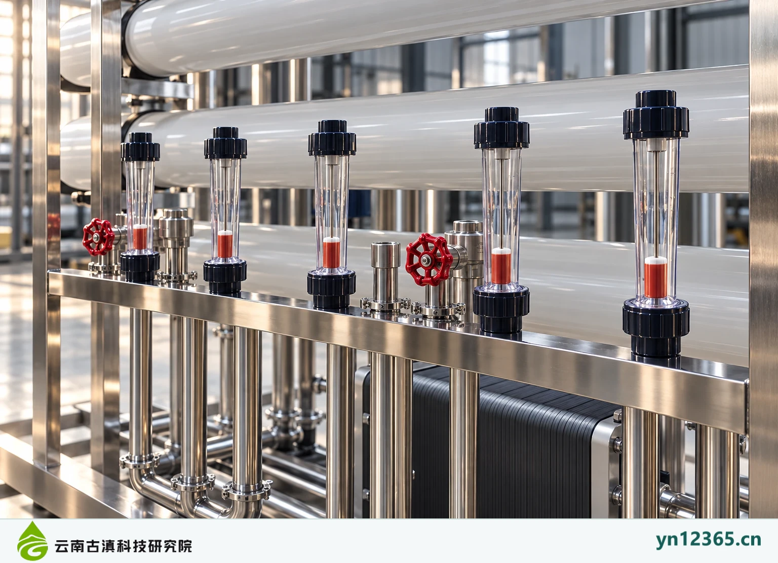
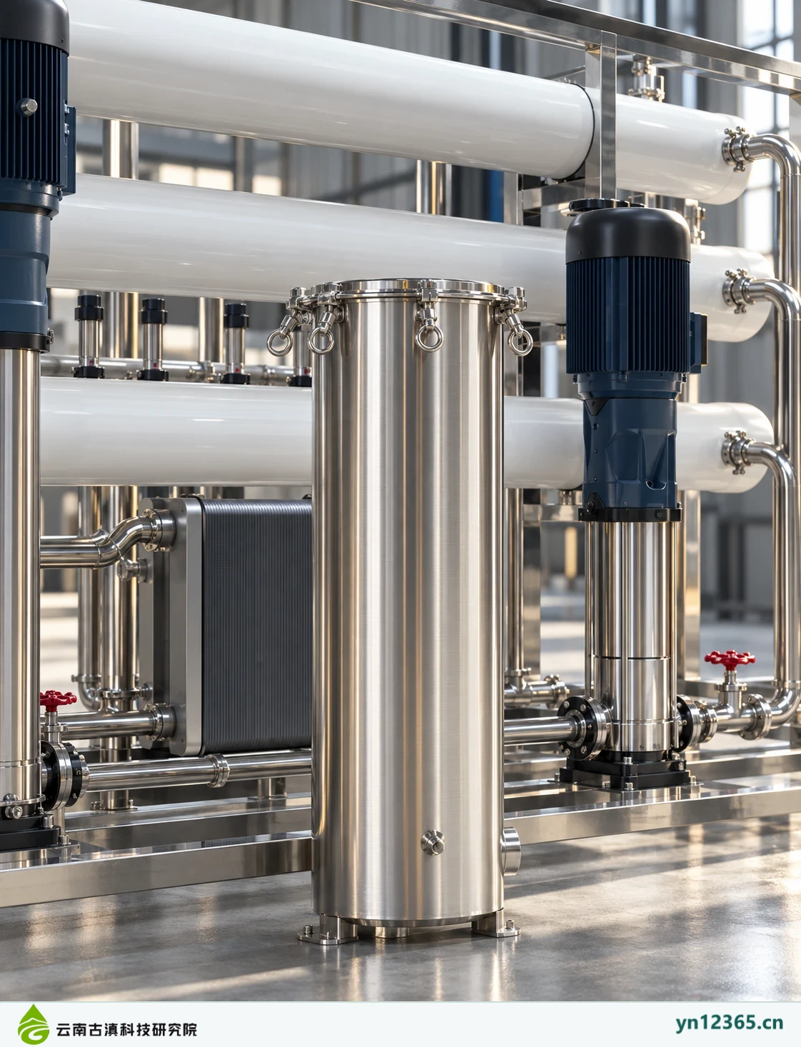
RO system layout and appearance (AI-assisted image 1; not a project photograph)
RO system · AI-assisted illustration 1. This image is not a customer-site photograph or evidence of model specifications or purification performance.
RO system layout and appearance (AI-assisted image 2; not a project photograph)
RO system · AI-assisted illustration 2. This image is not a customer-site photograph or evidence of model specifications or purification performance.
RO system layout and appearance (AI-assisted image 3; not a project photograph)
RO system · AI-assisted illustration 3. This image is not a customer-site photograph or evidence of model specifications or purification performance.
Stainless-steel water treatment equipment layout and appearance (AI-assisted image 1; not a project photograph)
Stainless-steel water treatment equipment · AI-assisted illustration 1. This image is not a customer-site photograph or evidence of model specifications or purification performance.
Stainless-steel water treatment equipment layout and appearance (AI-assisted image 2; not a project photograph)
Stainless-steel water treatment equipment · AI-assisted illustration 2. This image is not a customer-site photograph or evidence of model specifications or purification performance.
Stainless-steel water treatment equipment layout and appearance (AI-assisted image 3; not a project photograph)
Stainless-steel water treatment equipment · AI-assisted illustration 3. This image is not a customer-site photograph or evidence of model specifications or purification performance.
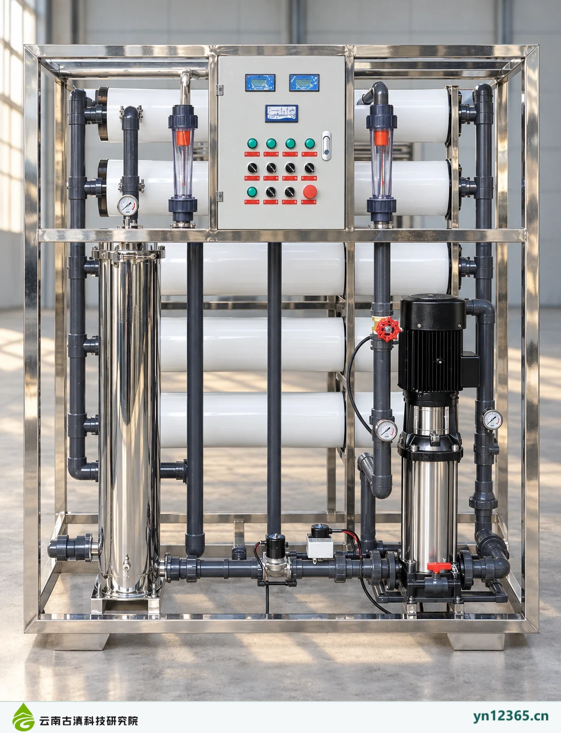
Layout and exterior illustration of a five-membrane RO unit (AI-assisted image 1; not a photograph of a project)
Five-membrane RO unit · AI-assisted illustration 1. AI-assisted image; not evidence of a customer site, model specifications, or purification performance.
Layout and exterior illustration of a five-membrane RO unit (AI-assisted image 2; not a photograph of a project)
Five-membrane RO unit · AI-assisted illustration 2. AI-assisted image; not evidence of a customer site, model specifications, or purification performance.
Layout and exterior illustration of a five-membrane RO unit (AI-assisted image 3; not a photograph of a project)
Five-membrane RO unit · AI-assisted illustration 3. AI-assisted image; not evidence of a customer site, model specifications, or purification performance.
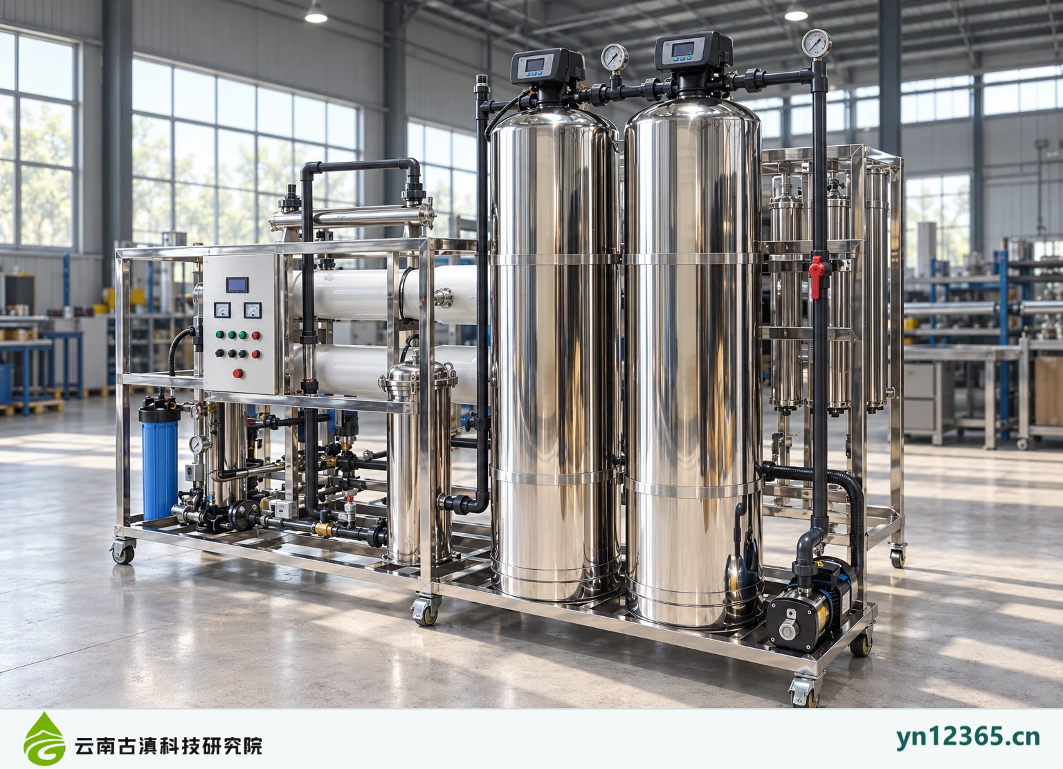
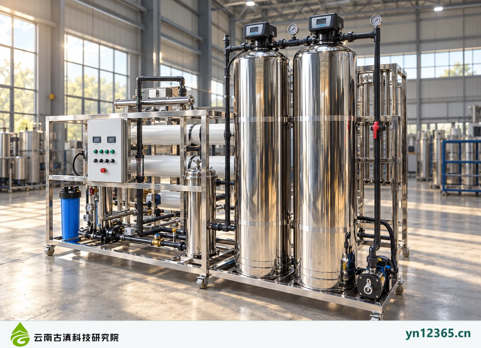
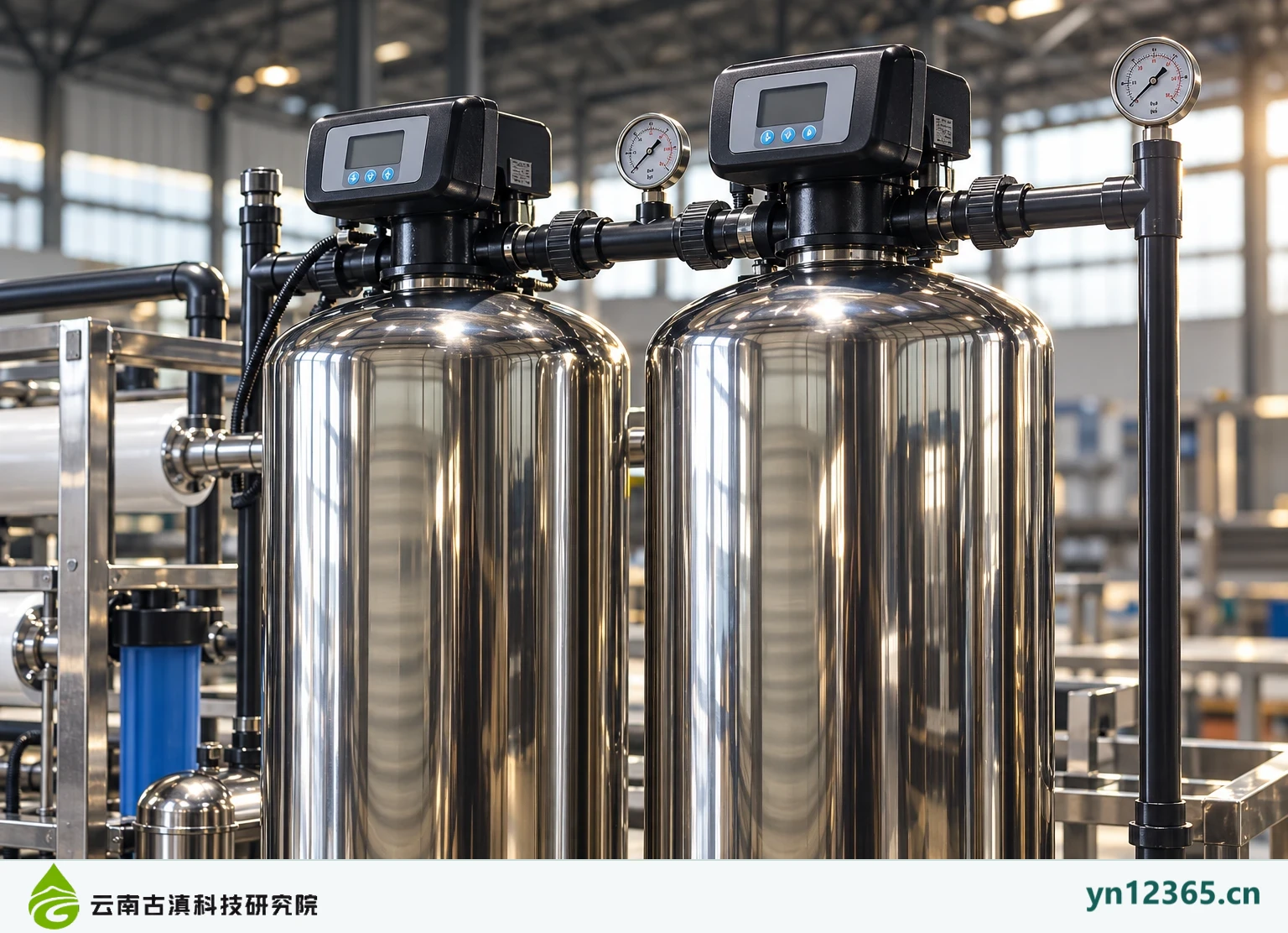
Layout and exterior illustration of an exhibition two-tank RO unit (AI-assisted image 1; not a photograph of a project)
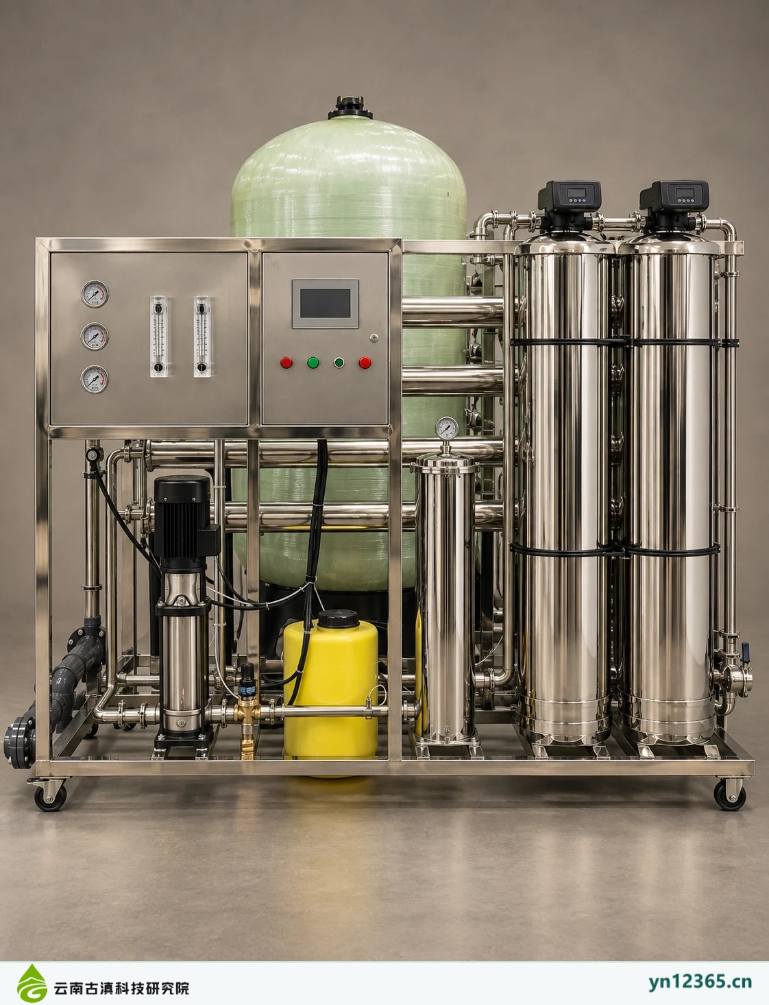
Exhibition two-tank RO unit · AI-assisted illustration 1. AI-assisted image; not evidence of a customer site, model specifications, or purification performance.
Layout and exterior illustration of an exhibition two-tank RO unit (AI-assisted image 2; not a photograph of a project)
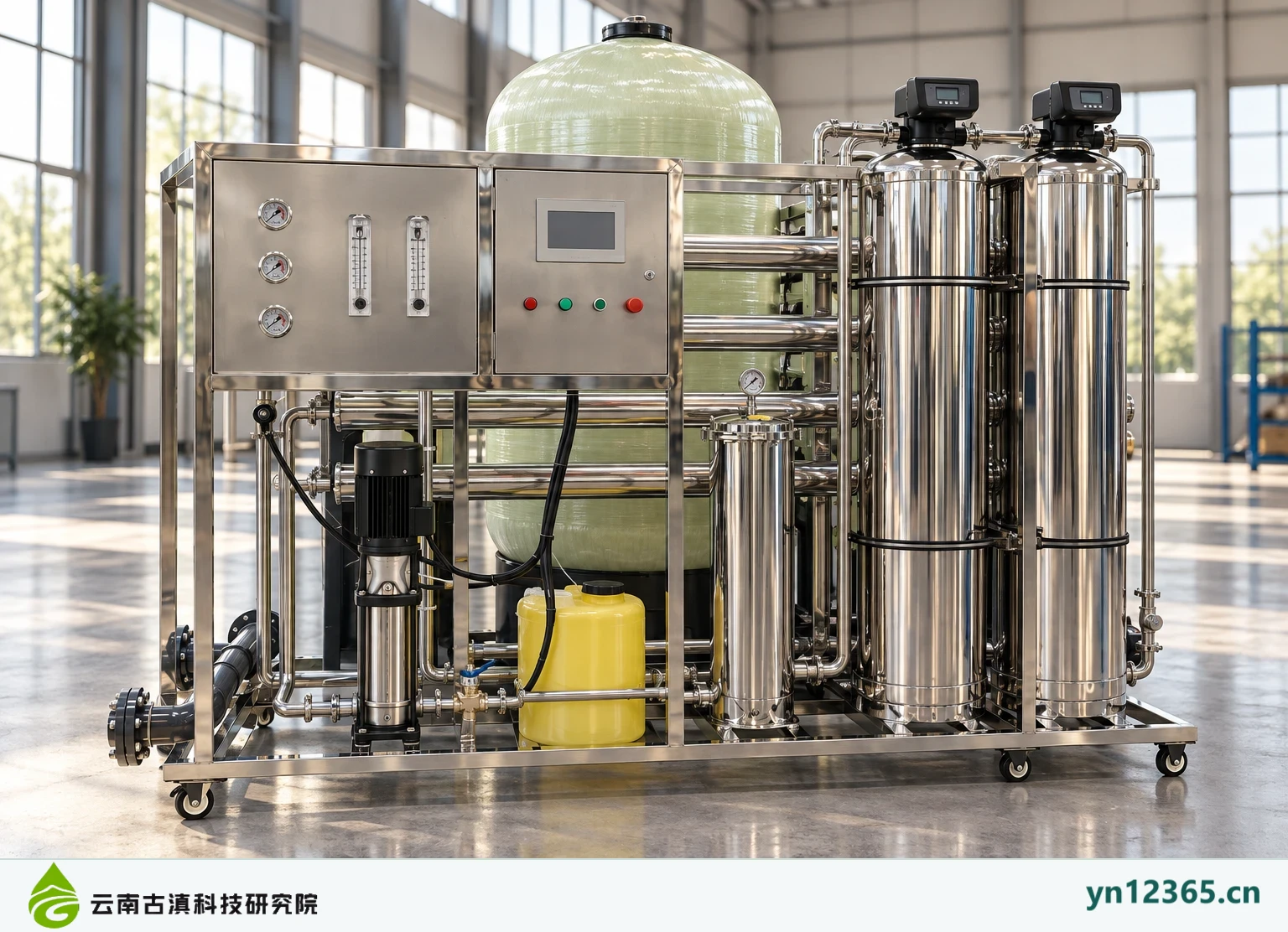
Exhibition two-tank RO unit · AI-assisted illustration 2. AI-assisted image; not evidence of a customer site, model specifications, or purification performance.
Layout and exterior illustration of an exhibition two-tank RO unit (AI-assisted image 3; not a photograph of a project)
Exhibition two-tank RO unit · AI-assisted illustration 3. AI-assisted image; not evidence of a customer site, model specifications, or purification performance.

Further checks

Complete gallery and selection navigation · Ask about actual equipment and supporting components

Content note:Prepared with AI assistance and checked against existing product category information and illustrations on October 4, 2026. This article supports discussions of requirements and documentation; it is not testing, licensing, a quotation, or evidence of results for a corresponding model. Confirm implementation according to product documents, actual operating conditions, and applicable requirements.

← Knowledge & resources
Contact & inquiries

Tell us about your water needs

Describe your water source, intended use, and water demand so technical staff can prepare advice.

Discuss your water treatment requirements ↗