Filtration and softening equipment gallery: understanding vessels, valves, and ultrafiltration layouts
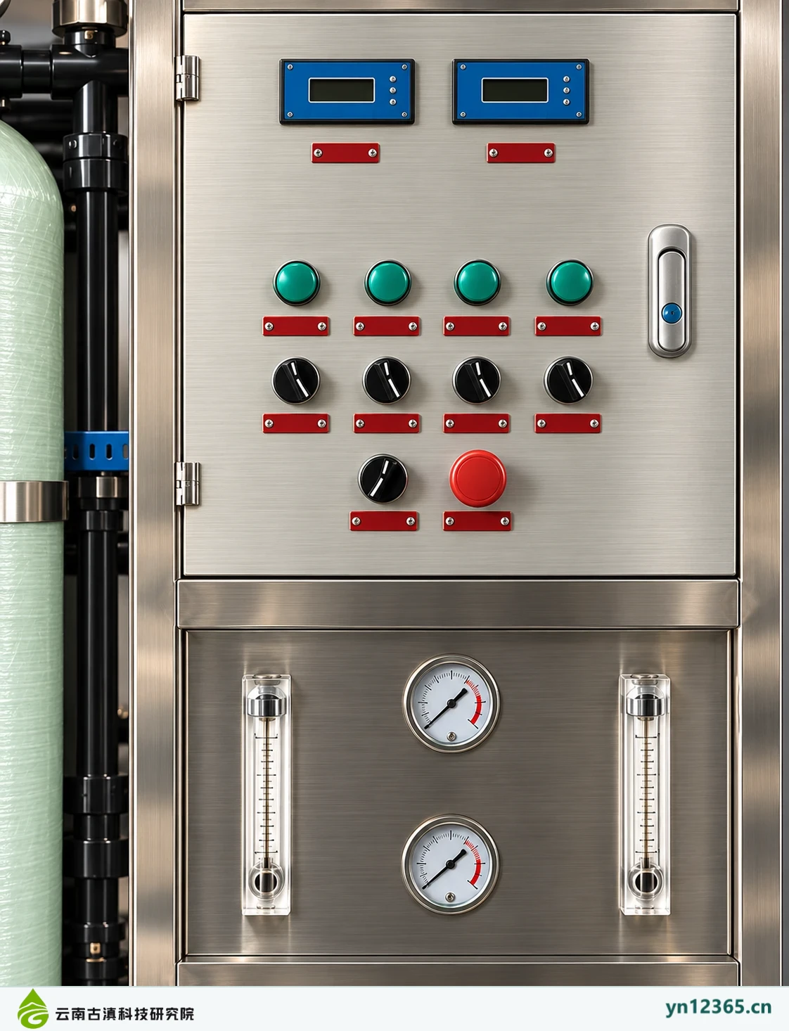
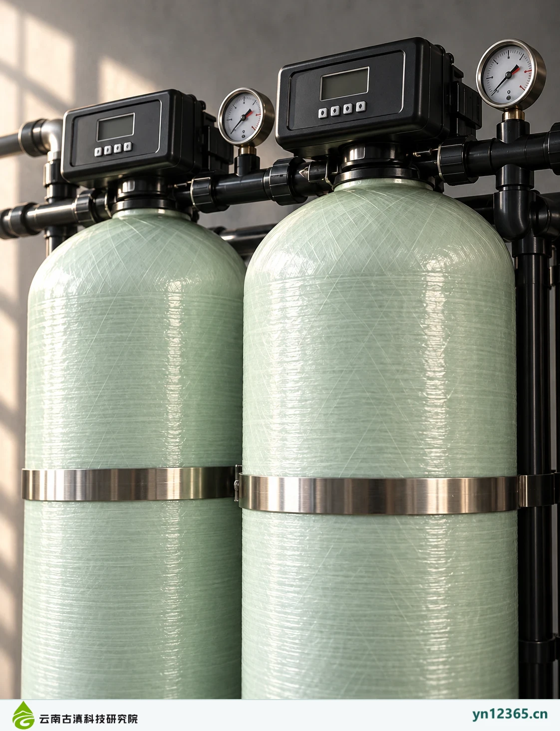
These images are organized by tank filtration, FRP equipment, and ultrafiltration modules to identify structural and maintenance questions for further discussion. Tank count, color, and appearance do not establish internal media or imply equal treatment capacities across equipment groups.
Published · 2026-10-04Updated ·
Category gallery · All images are AI-assisted illustrations, not actual customer project photographs
These images are organized by tank filtration, FRP equipment, and ultrafiltration modules to identify structural and maintenance questions for further discussion. Tank count, color, and appearance do not establish internal media or imply equal treatment capacities across equipment groups.
Similar appearances may serve different tasks
Filtration, softening, ultrafiltration, and other tasks require specific material, membrane, and system documentation. Tanks and valves in images provide visual information only. Color does not establish material, and tank count does not establish water production capacity. Place raw water, application, and downstream objectives alongside images when describing requirements.
Keep maintenance questions in mind while viewing
Ask which site conditions are needed for valve servicing, media replacement, backwashing, drainage, and module maintenance. Front views do not show all connections or maintenance scope. Consult corresponding documentation for actual dimensions and allowable conditions. Candidate configuration changes require versions. Images do not replace media loading and connection information.
Equipment and scene illustrations
Click an image to view it at full size. Images are for discussing layouts and requirements only. Confirm models, parameters, and delivery against corresponding documentation.
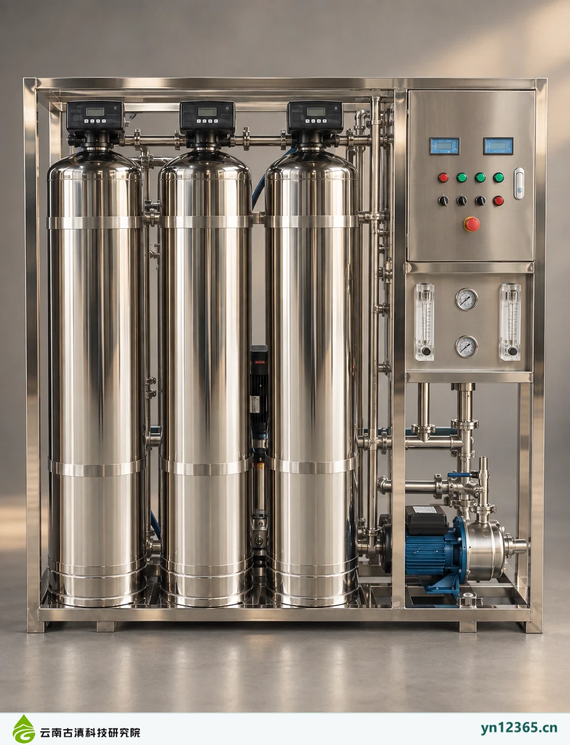
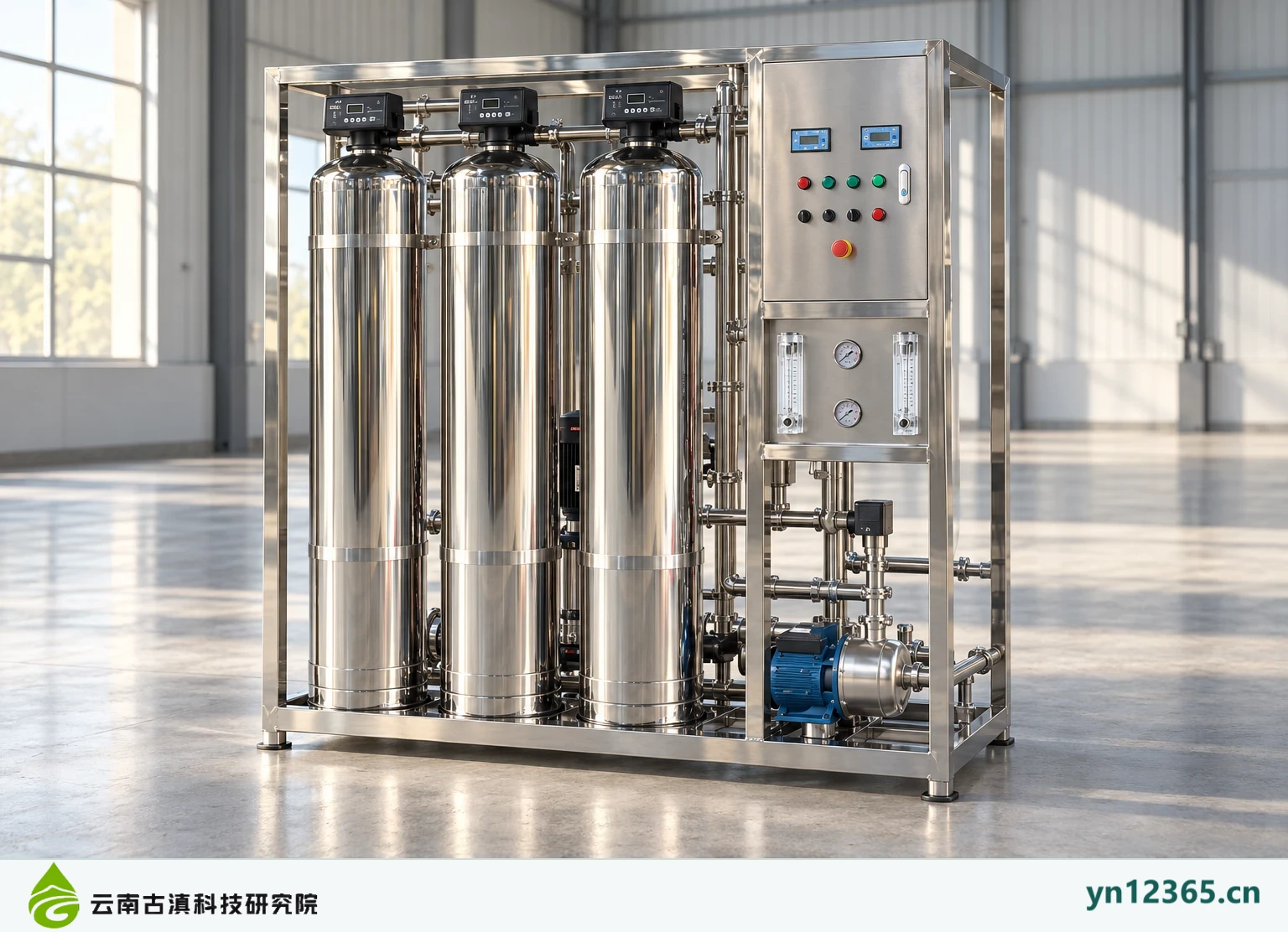
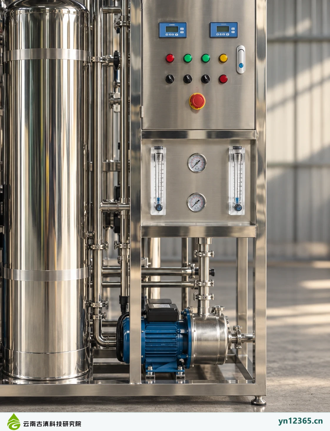
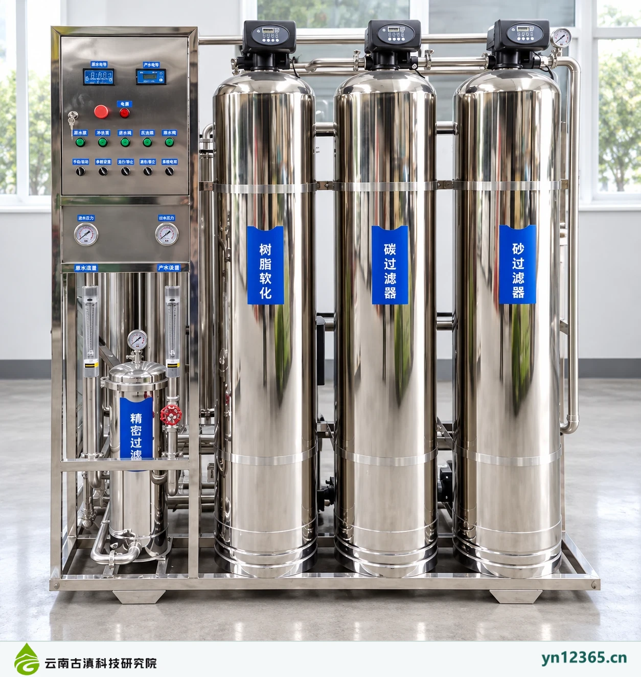
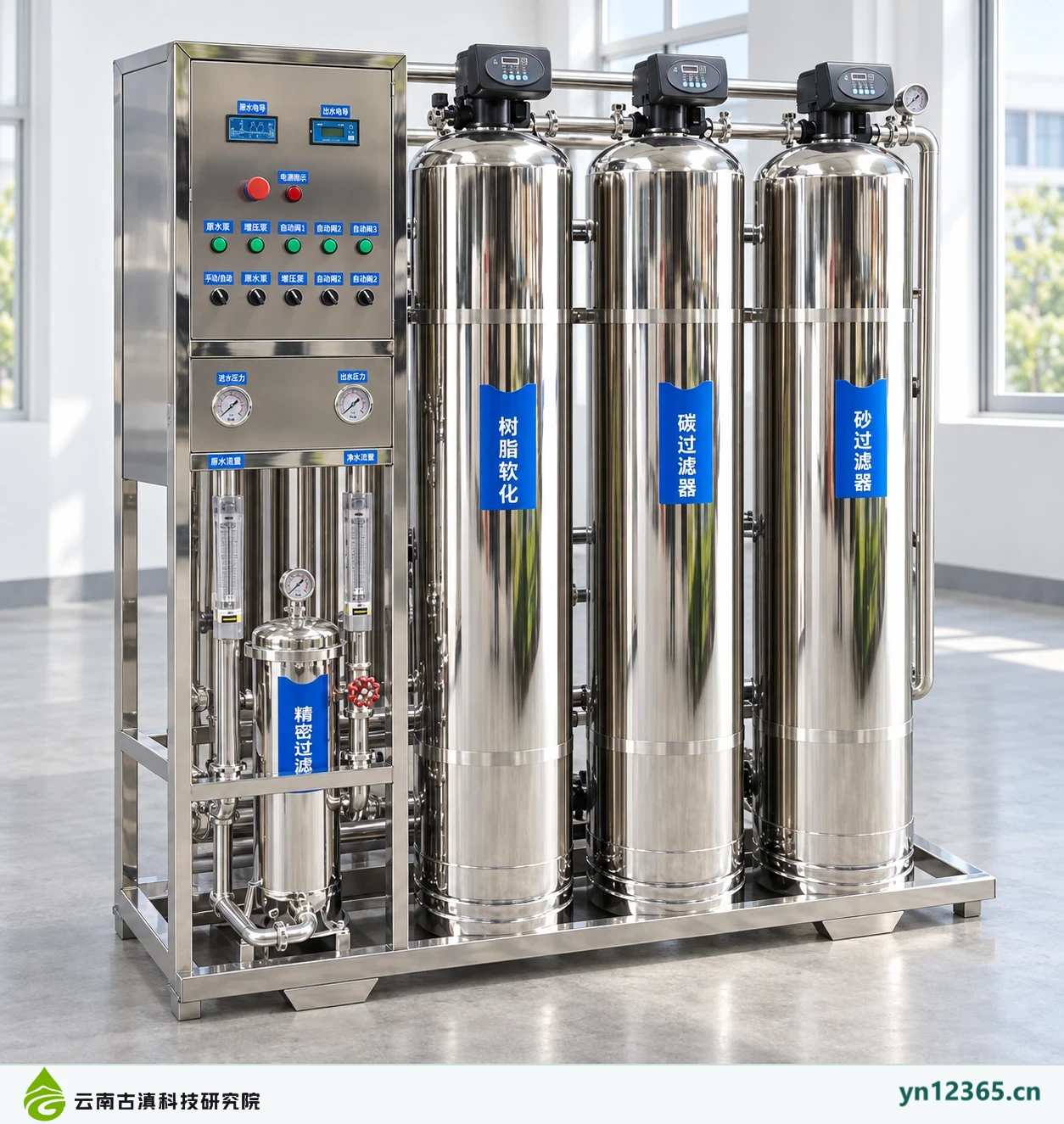
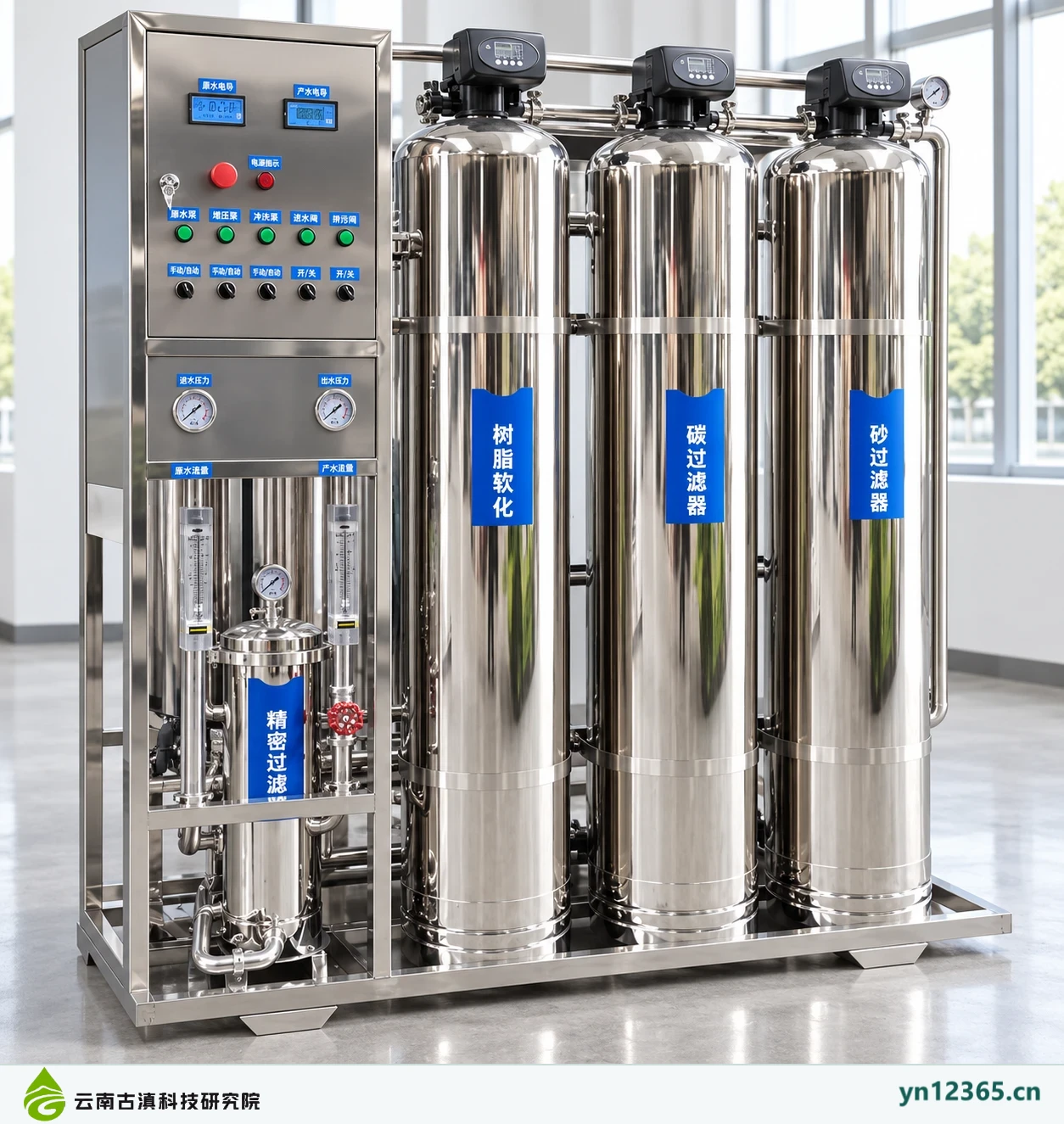
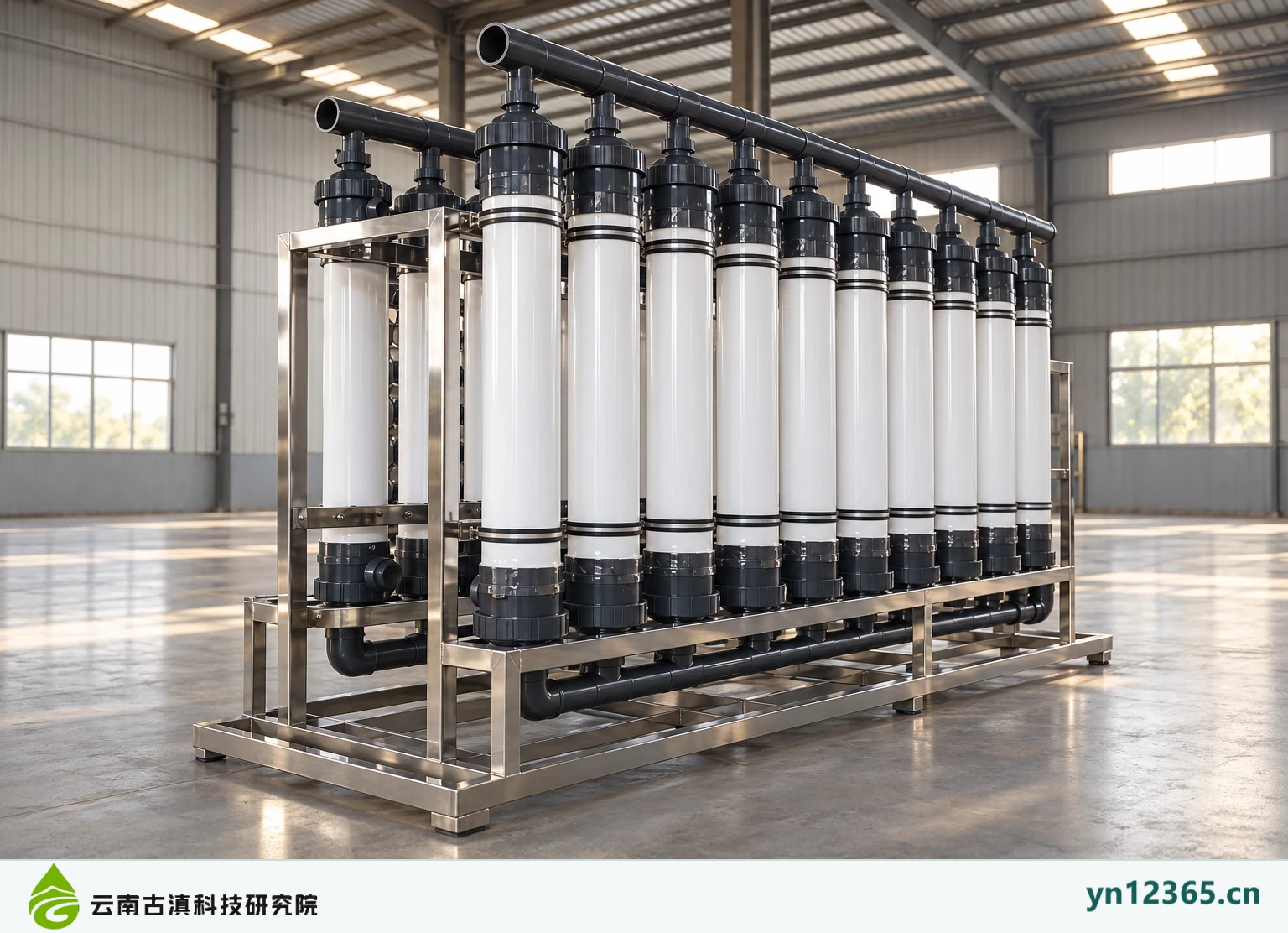
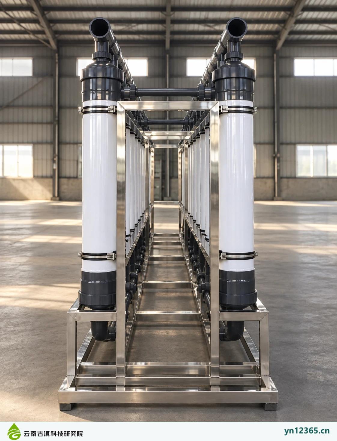
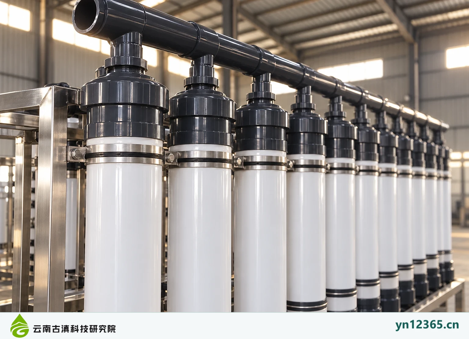
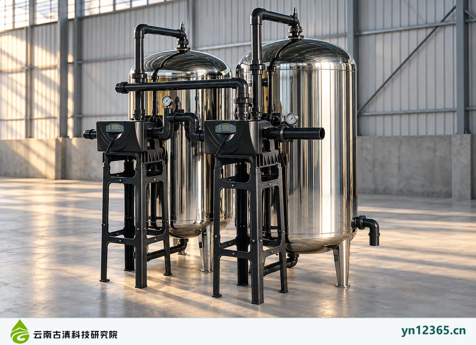
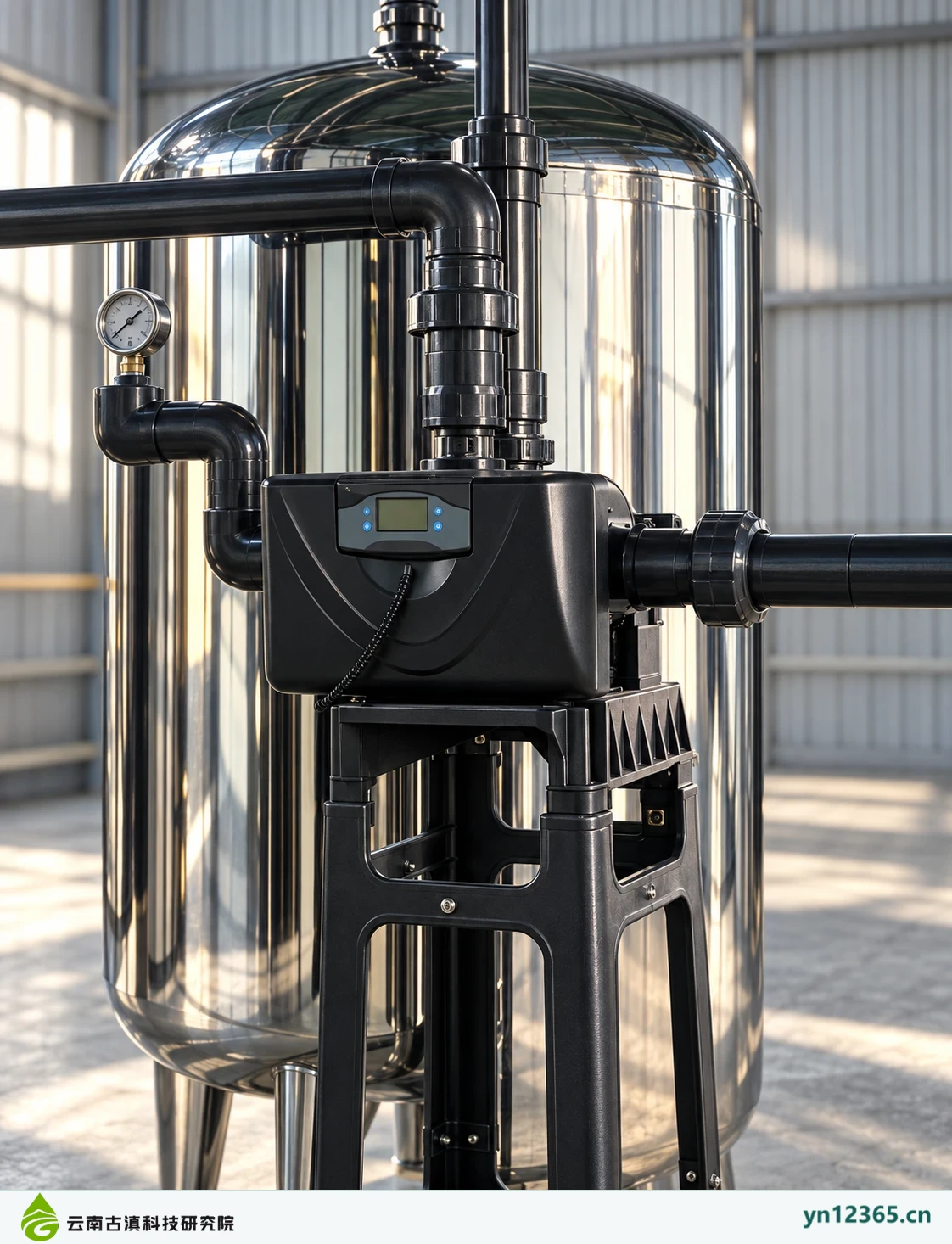
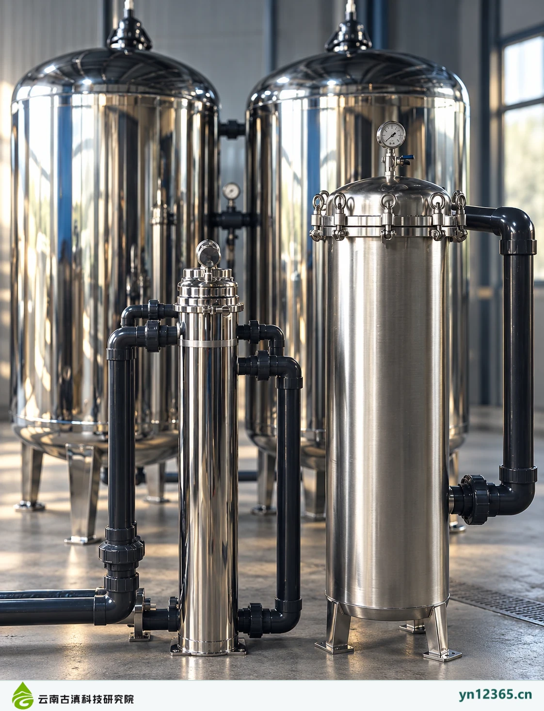
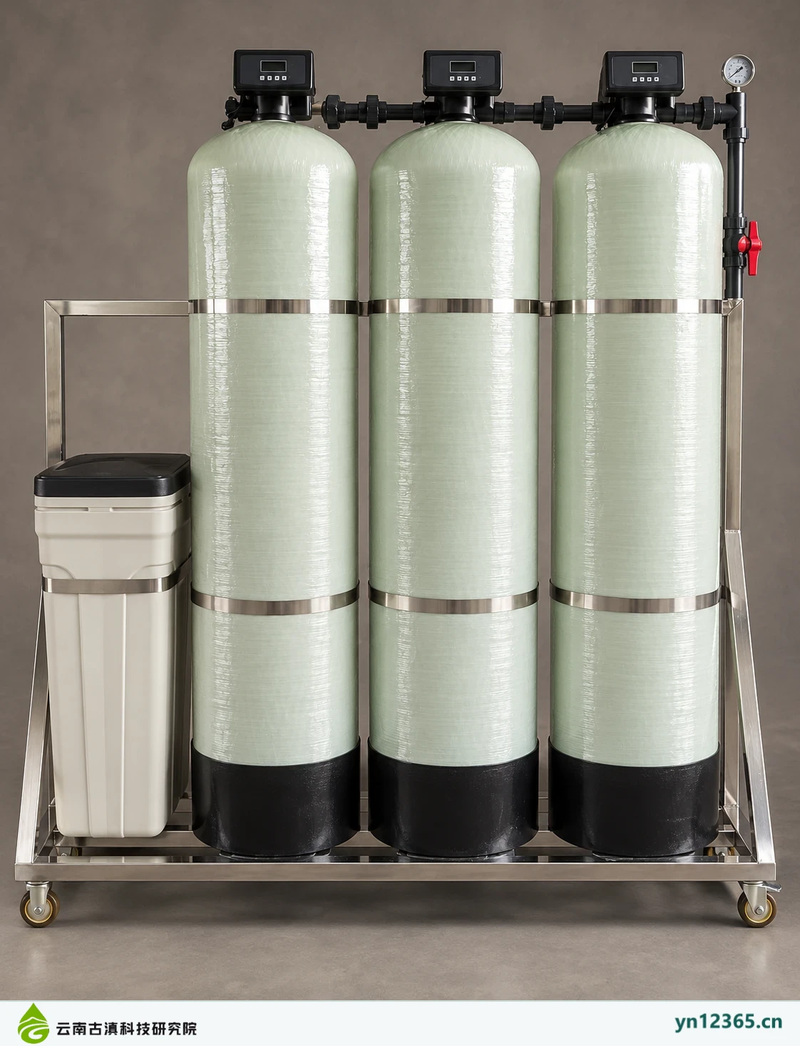
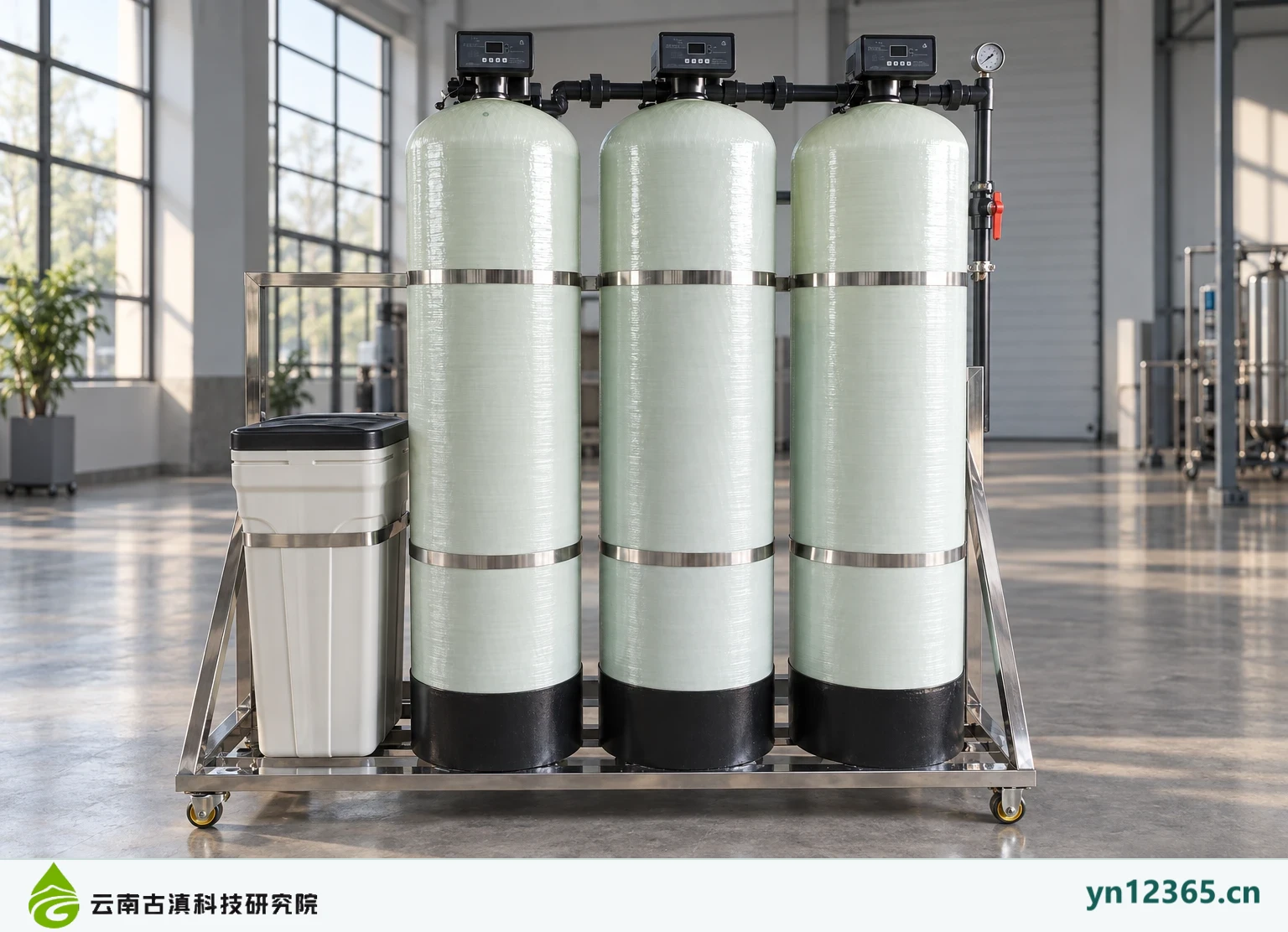
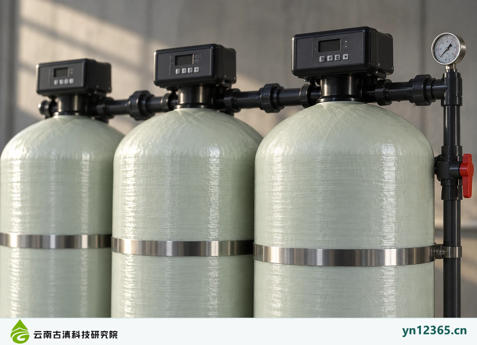
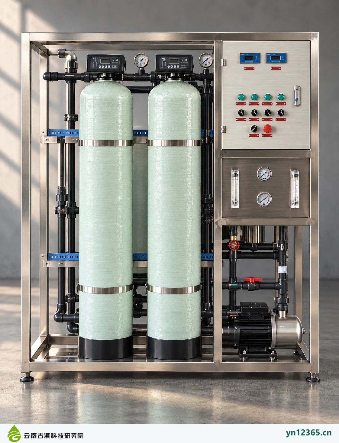
Three-tank automatic filtration unit · AI-assisted illustration 1. AI-assisted image; not evidence of a customer site, model specifications, or purification performance.Three-tank automatic filtration unit · AI-assisted illustration 2. AI-assisted image; not evidence of a customer site, model specifications, or purification performance.Three-tank automatic filtration unit · AI-assisted illustration 3. AI-assisted image; not evidence of a customer site, model specifications, or purification performance.Stainless steel three-tank filtration equipment · AI-assisted illustration 1. AI-assisted image; not evidence of a customer site, model specifications, or purification performance.Stainless steel three-tank filtration equipment · AI-assisted illustration 2. AI-assisted image; not evidence of a customer site, model specifications, or purification performance.Stainless steel three-tank filtration equipment · AI-assisted illustration 3. AI-assisted image; not evidence of a customer site, model specifications, or purification performance.Dual-row UF unit · AI-assisted illustration 1. This image is not a customer-site photograph or evidence of model specifications or purification performance.Dual-row UF unit · AI-assisted illustration 2. This image is not a customer-site photograph or evidence of model specifications or purification performance.Dual-row UF unit · AI-assisted illustration 3. This image is not a customer-site photograph or evidence of model specifications or purification performance.Two-tank filtration equipment · AI-assisted illustration 1. AI-assisted image; not evidence of a customer site, model specifications, or purification performance.Two-tank filtration equipment · AI-assisted illustration 2. AI-assisted image; not evidence of a customer site, model specifications, or purification performance.Two-tank filtration equipment · AI-assisted illustration 3. AI-assisted image; not evidence of a customer site, model specifications, or purification performance.Three-tank FRP softening and filtration unit · AI-assisted illustration 1. This image is not a customer-site photograph or evidence of model specifications or purification performance.Three-tank FRP softening and filtration unit · AI-assisted illustration 2. This image is not a customer-site photograph or evidence of model specifications or purification performance.Three-tank FRP softening and filtration unit · AI-assisted illustration 3. This image is not a customer-site photograph or evidence of model specifications or purification performance.Twin-tank FRP unit · AI-assisted illustration 1. This image is not a customer-site photograph or evidence of model specifications or purification performance.Twin-tank FRP unit · AI-assisted illustration 2. This image is not a customer-site photograph or evidence of model specifications or purification performance.Twin-tank FRP unit · AI-assisted illustration 3. This image is not a customer-site photograph or evidence of model specifications or purification performance.
Content note:Prepared with AI assistance and checked against existing product category information and illustrations on October 4, 2026. This article supports discussions of requirements and documentation; it is not testing, licensing, a quotation, or evidence of results for a corresponding model. Confirm implementation according to product documents, actual operating conditions, and applicable requirements.