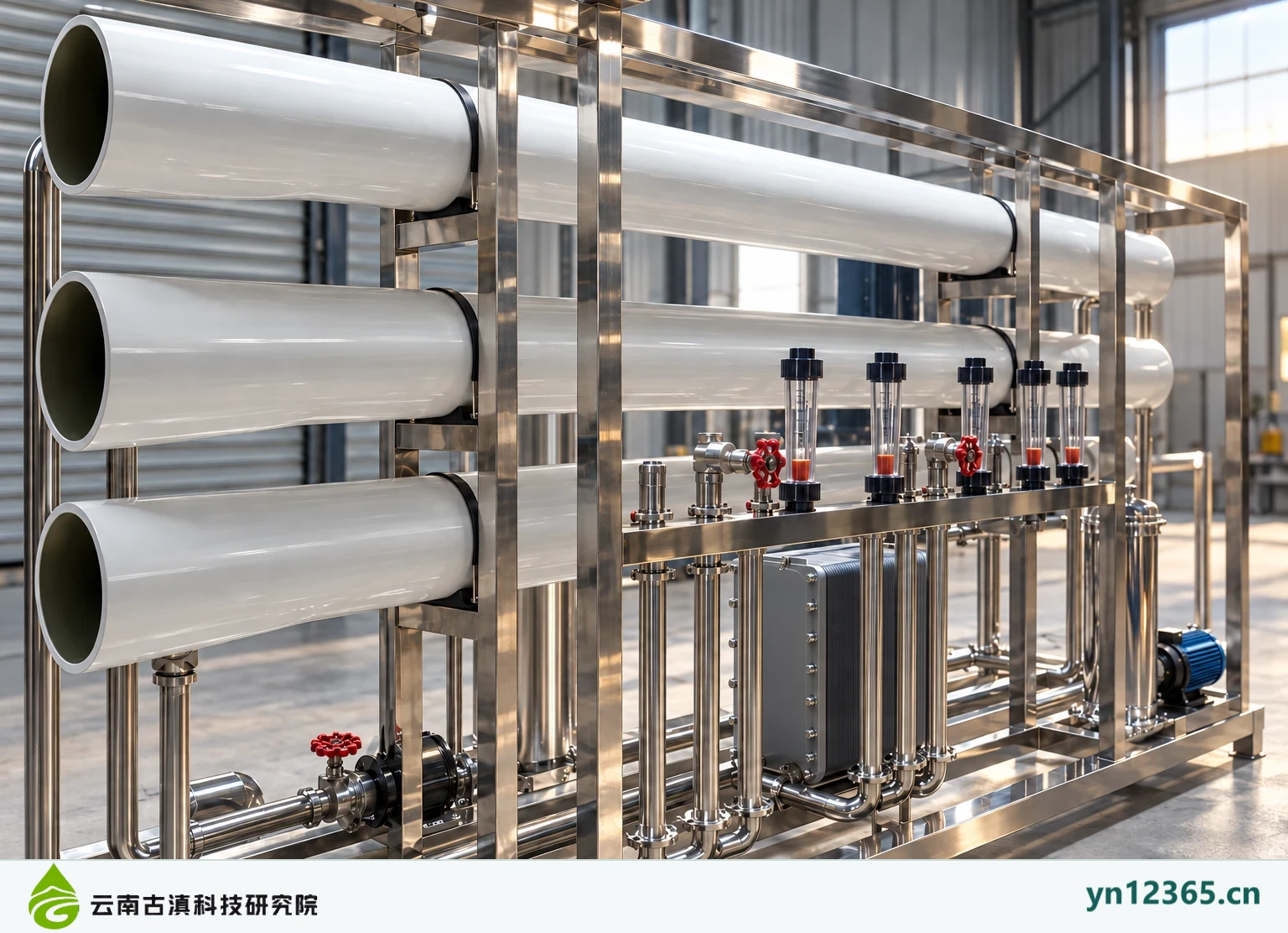
Specifications
| Display type | Configuration overview; not a specific model offered for supply |
|---|---|
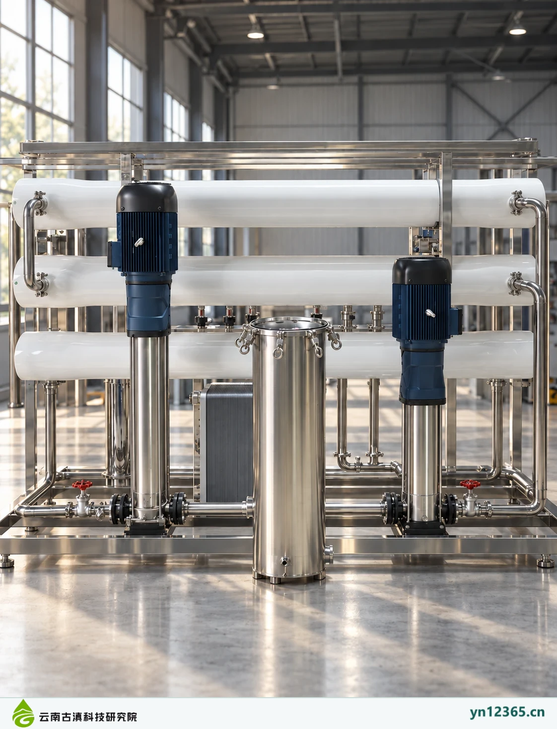
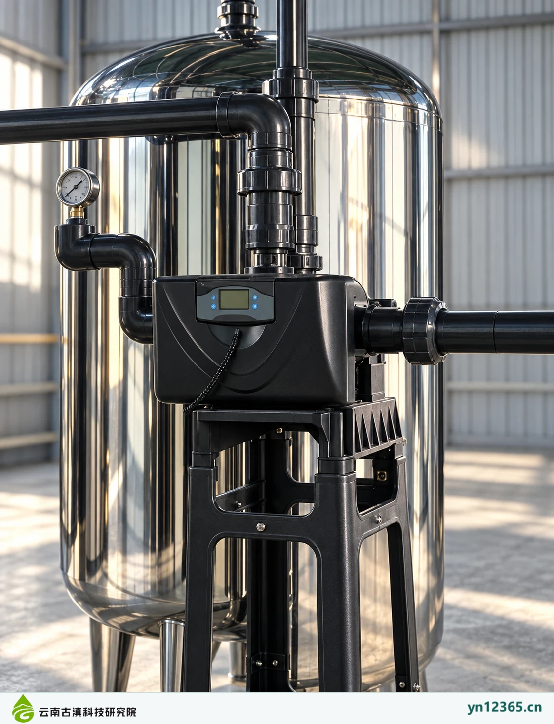
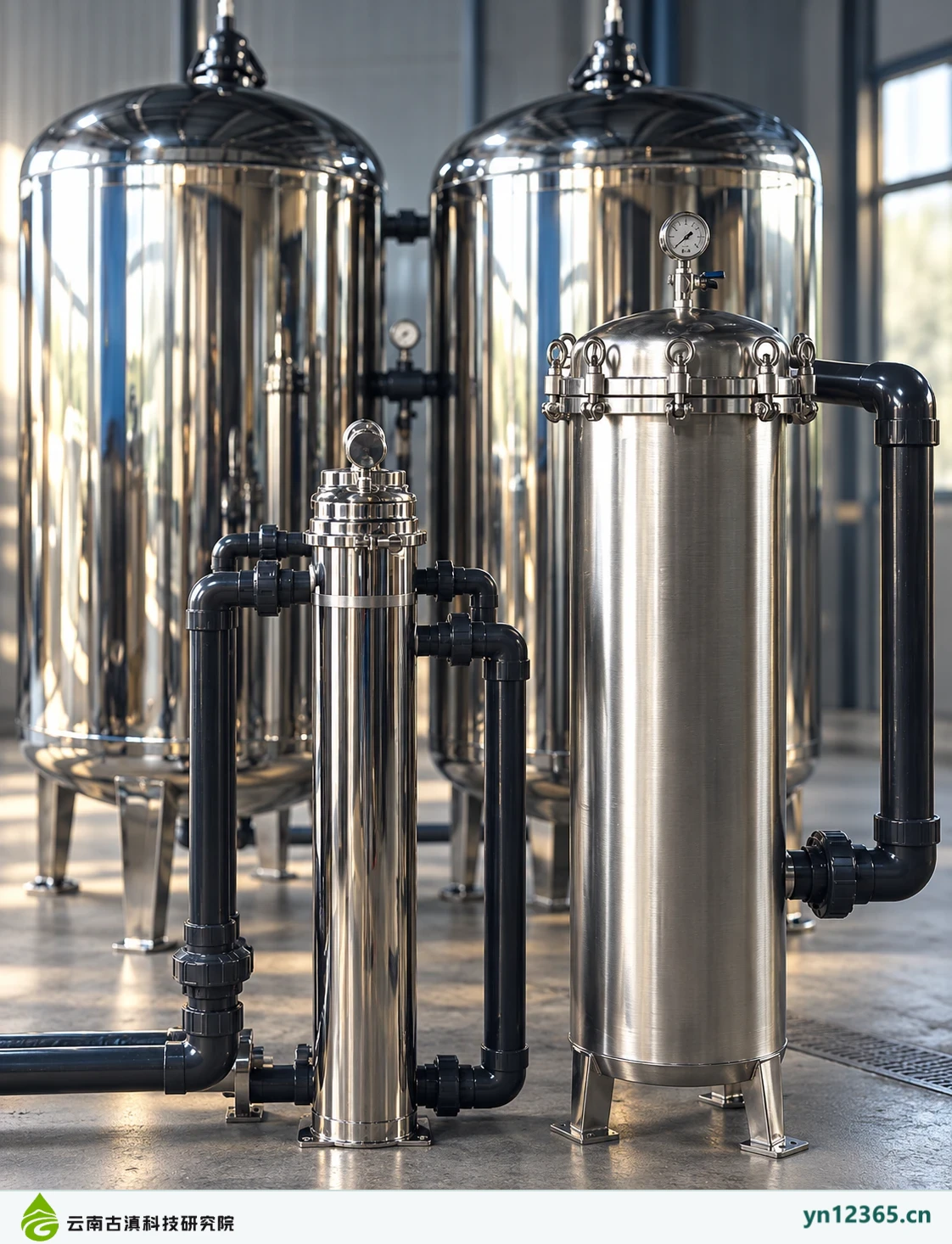
| Image source | AI-assisted illustrations, not photographs of customer sites |
| Basis for compatibility assessment | Feedwater, actual application, complete model information and site conditions |
| Model specifications and delivery | Subject to the confirmed product documentation and written scope for the order |
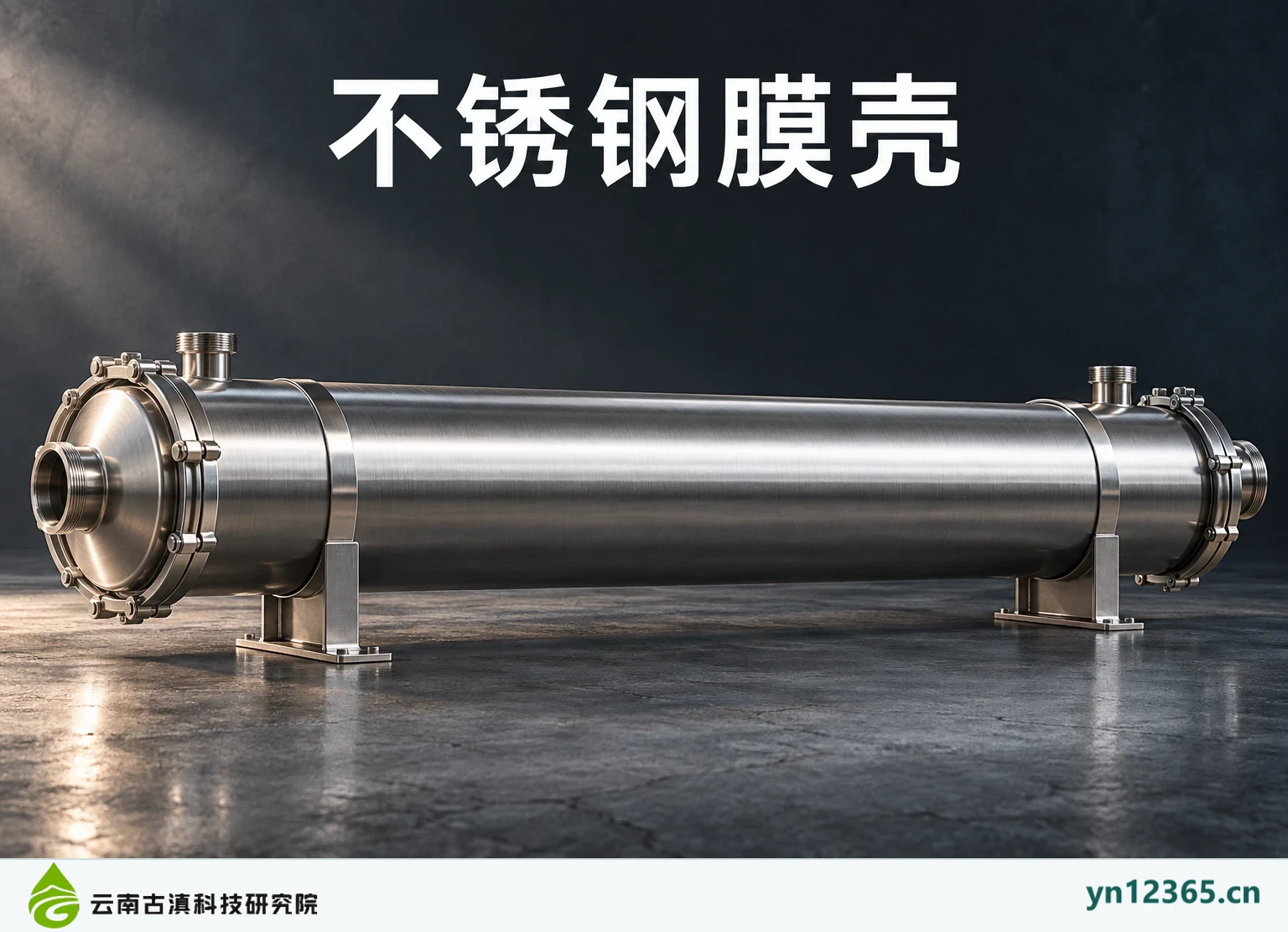
A membrane pressure vessel supports membrane element installation and pressure containment. Its dimensions, connections, and allowable conditions must match the membrane and system. Detail illustrations show connections and installation directions; they do not establish vessel material, pressure rating, or internal elements.
Applications and the starting point for selection
For new installations or replacement, obtain the complete vessel model and membrane configuration documentation. Similar appearances do not mean components are interchangeable. Do not order solely from photographs, diameter descriptions, or the number of housings.
Equipment, interfaces and site conditions
Check membrane loading dimensions, inlet and outlet arrangements, end fittings, and maintenance direction. State whether seals and mounting hardware are included. Obtain actual pressure limits and installation requirements from the corresponding product documentation.
Maintenance and handover
All assembly and disassembly must be performed by appropriate personnel under safe site conditions and in accordance with the product instructions. This page provides no procedures for work under pressure. After replacement, check connections, operation, and test records against system requirements.
| Item to check | Information and operating basis |
|---|---|
| Complete vessel model | Obtain documentation for the relevant model or site and record the source, date, applicable conditions and person responsible. Leave incomplete information pending confirmation. |
| Membrane loading and connection documentation | Obtain documentation for the relevant model or site and record the source, date, applicable conditions and person responsible. Leave incomplete information pending confirmation. |
| Allowable operating conditions and compatible seals | Obtain documentation for the relevant model or site and record the source, date, applicable conditions and person responsible. Leave incomplete information pending confirmation. |
| End servicing and removal direction | Obtain documentation for the relevant model or site and record the source, date, applicable conditions and person responsible. Leave incomplete information pending confirmation. |
Illustrative configurations and detail gallery
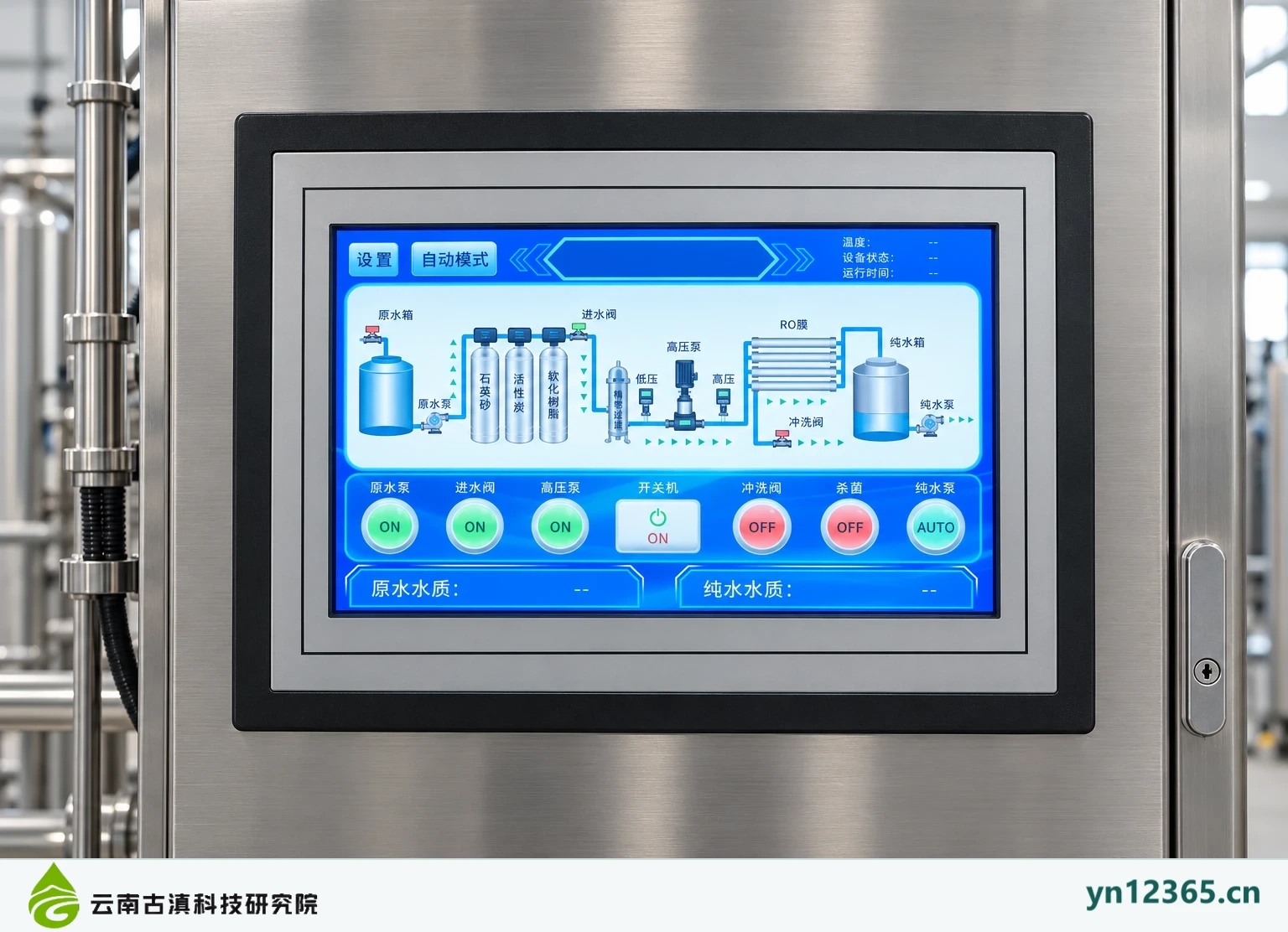
Select an image to see the full view. The images illustrate configuration topics and do not represent a single completed project. Do not infer specifications from component counts, colors or screen readings.
Related products and further reading
Read implementation or maintenance information for this equipment · Equipment and consumables resource directory · Send your actual requirements
Scope of this information:Compiled on 4 October 2026 from the available equipment-themed material. Equipment images are AI-assisted illustrations. This page presents possible configurations and is not evidence of a specific model, supply list, test approval, licence or completed project. The actual model, operating conditions and intended use must be confirmed against the relevant documentation. Prices, warranty and installation scope are subject to the written agreement for each order.
Additional product and system illustrations
These additional illustrations show component forms and system arrangements. Open an image for the full view. Check the actual model, connections, materials, and treatment task against the relevant documentation.
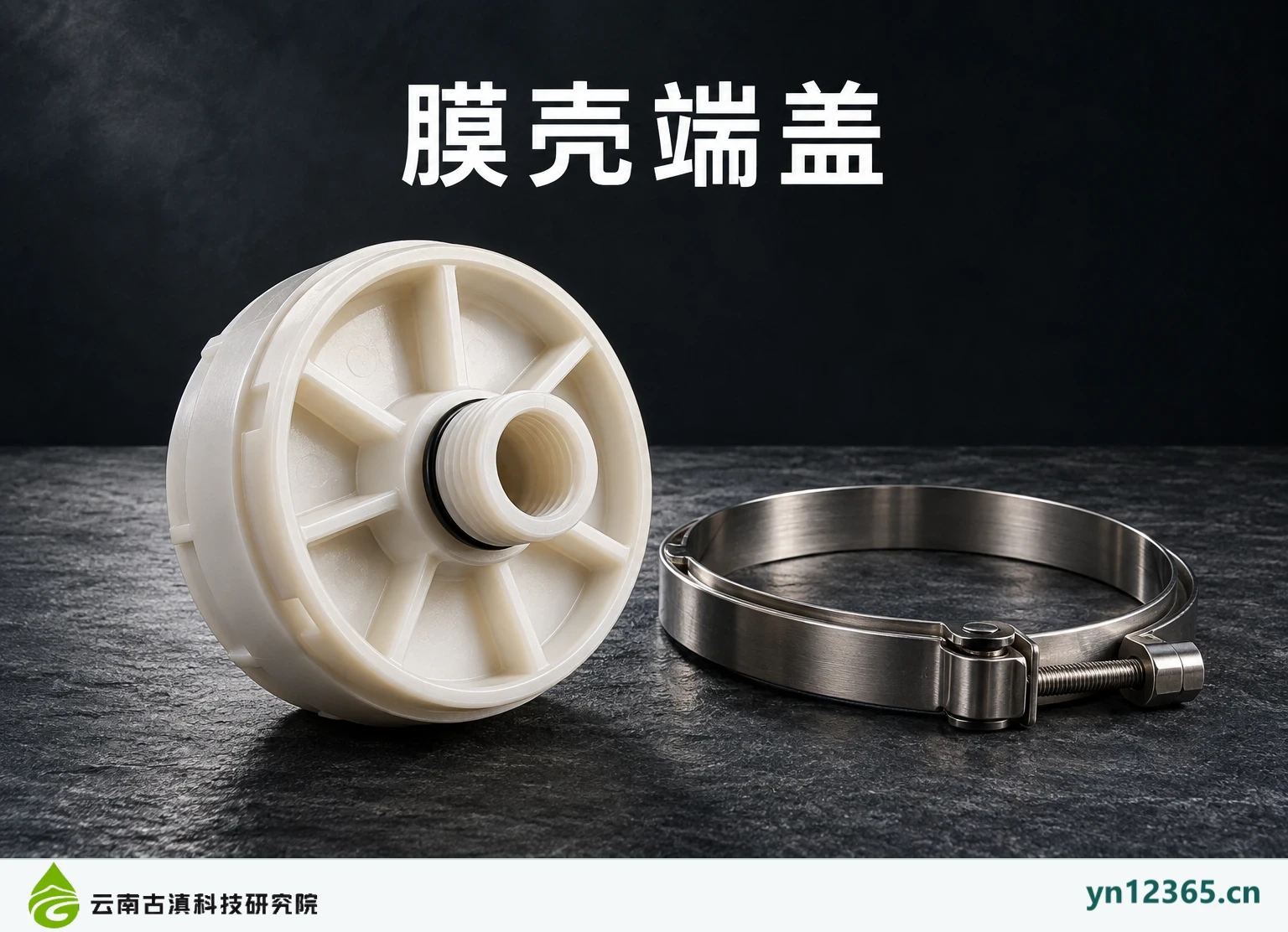
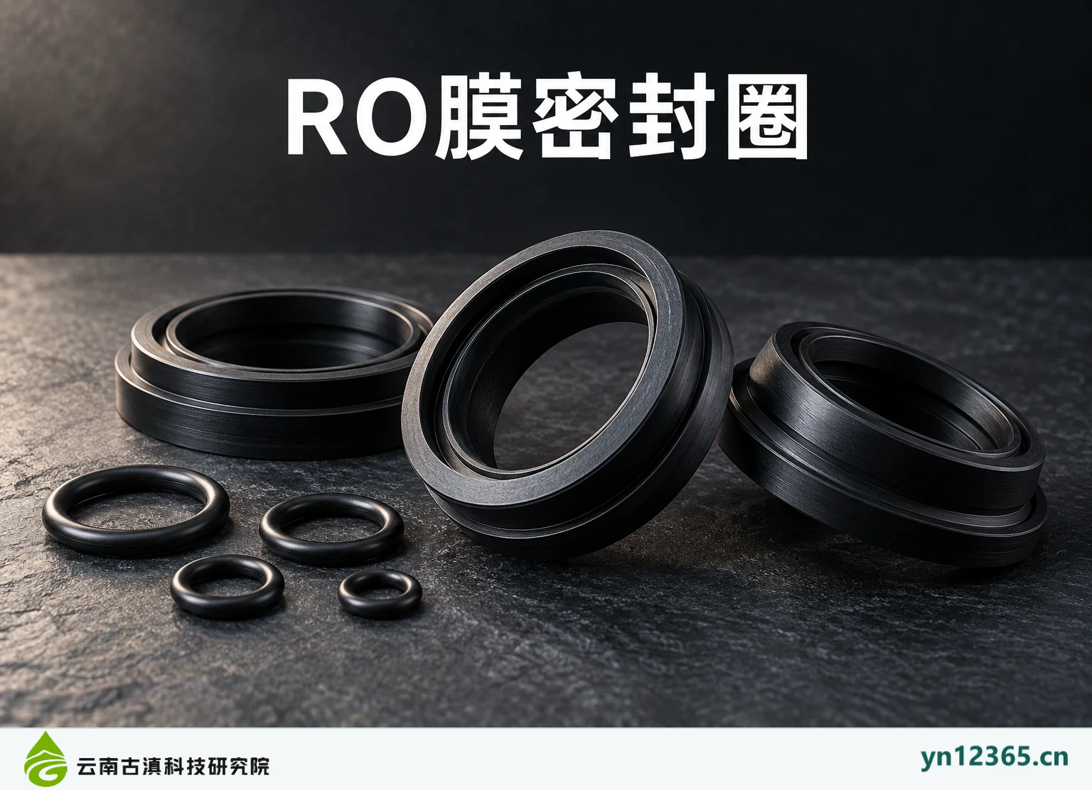
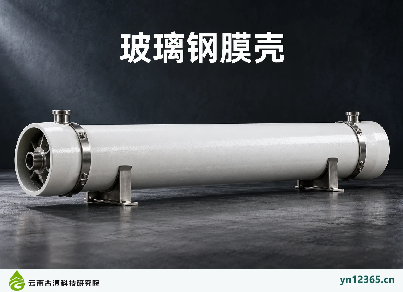
Product and application galleries · Equipment & consumable categories · Describe your actual water requirements
Document and image sources:Compiled on October 5, 2026, from product-themed materials and their generation notes provided by the user. Images are AI-assisted illustrations, not photographs of customer projects. This page supports discussion of product categories, selection, and maintenance. Confirm specific models, performance, testing, prices, warranties, and supply scope against the relevant product documents and written agreement.