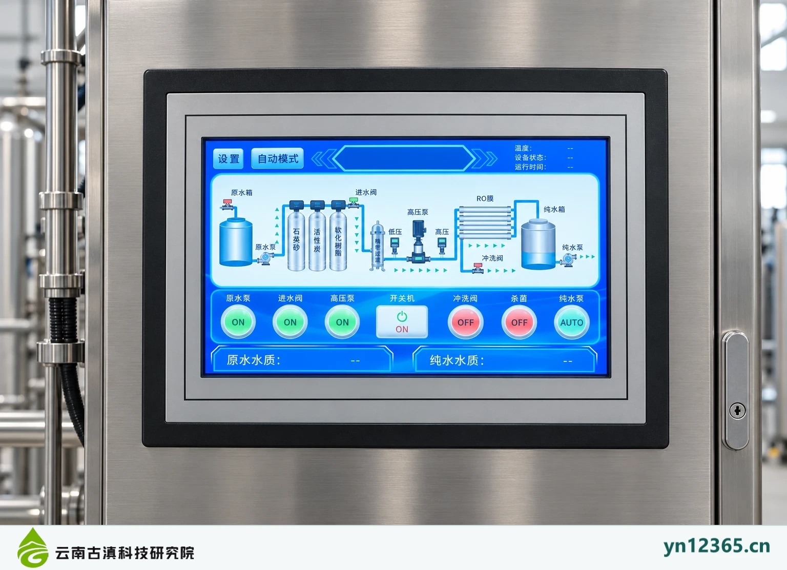
Specifications
| Display type | Configuration overview; not a specific model offered for supply |
|---|---|
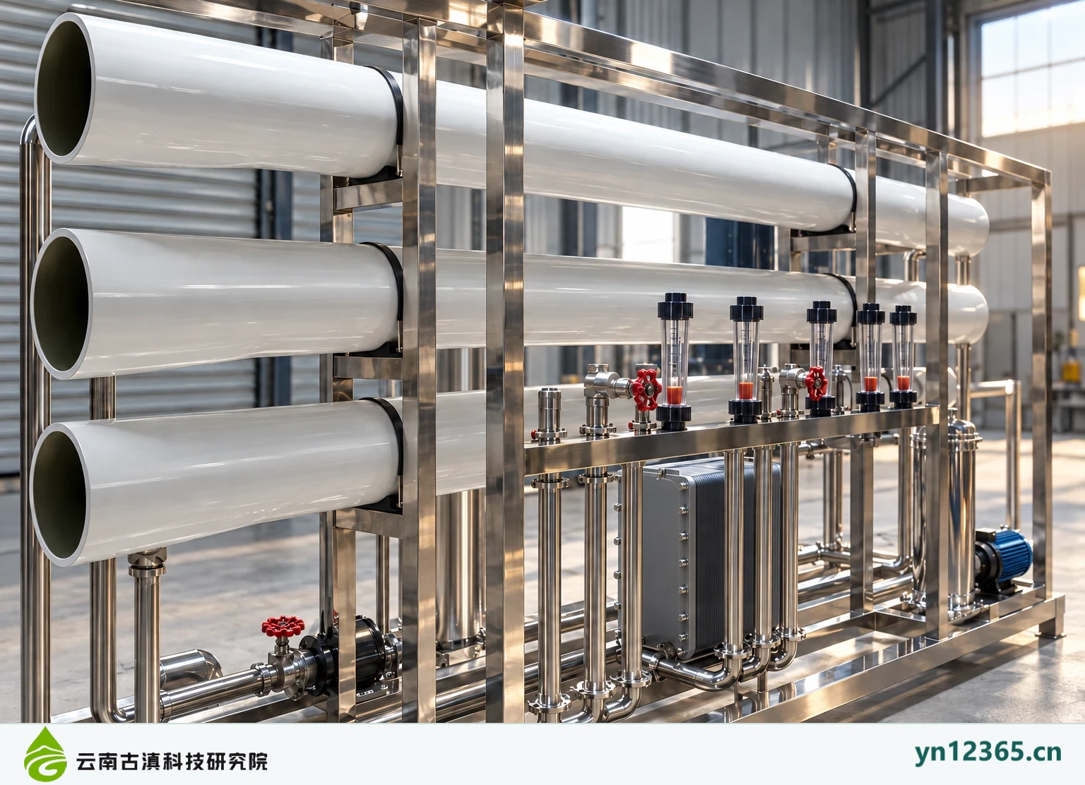
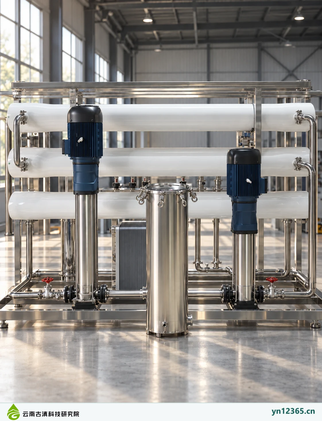
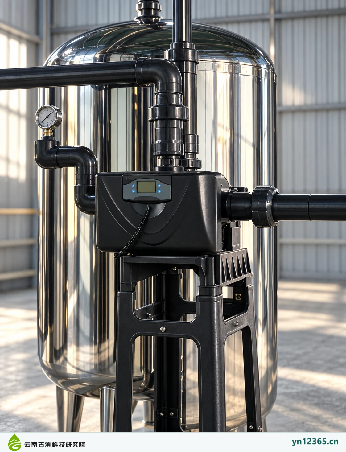
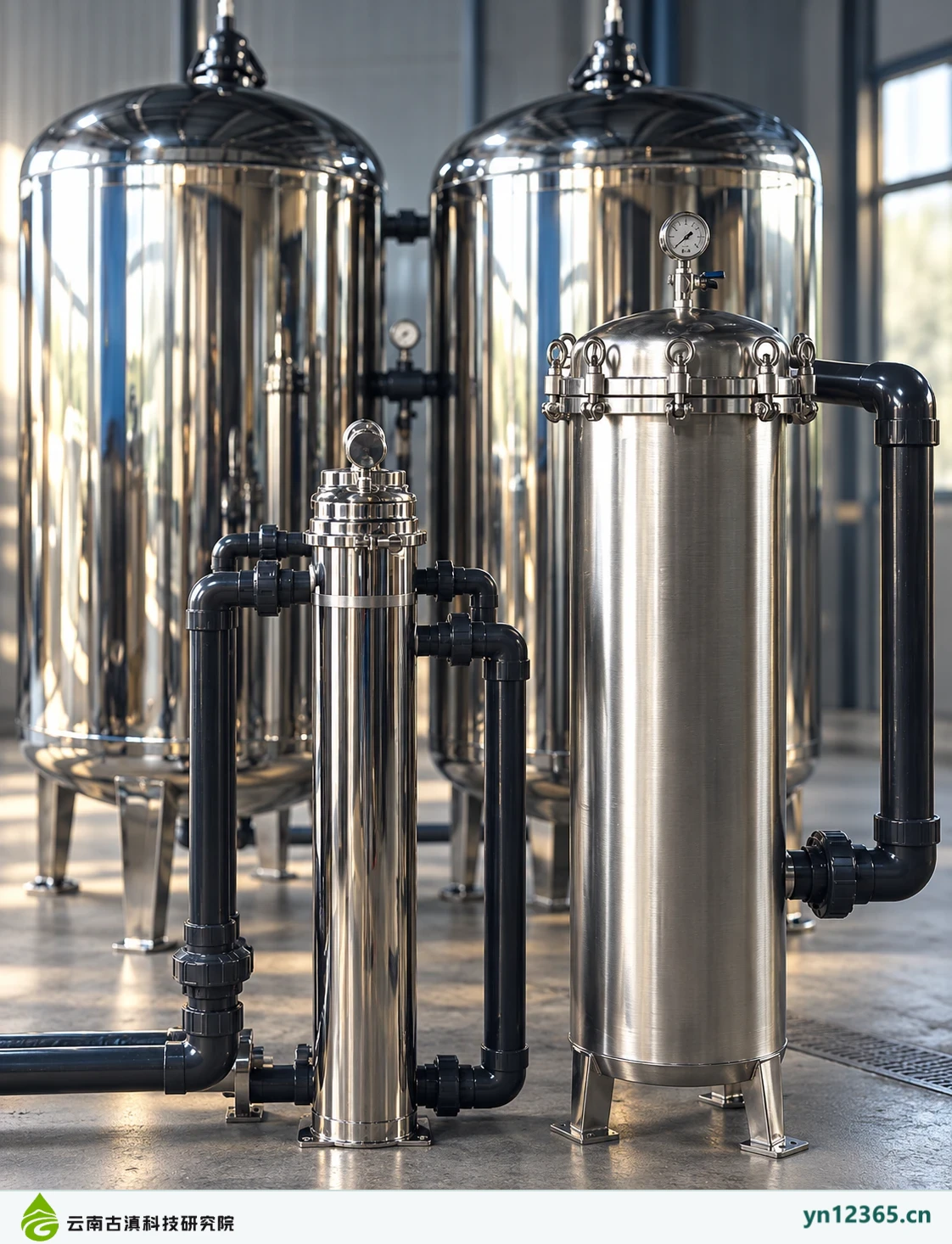
| Image source | AI-assisted illustrations, not photographs of customer sites |
| Basis for compatibility assessment | Feedwater, actual application, complete model information and site conditions |
| Model specifications and delivery | Subject to the confirmed product documentation and written scope for the order |
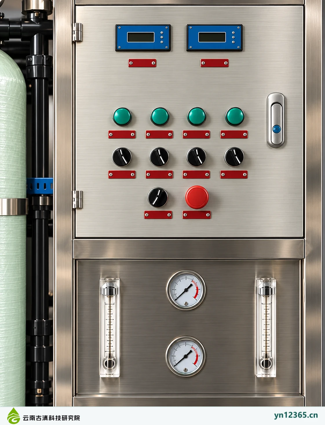
A control cabinet should implement system operation and alarm requirements through traceable electrical and control documentation. Illustrations of screens, buttons, and dials help discuss operator locations only. They do not establish smart connectivity, remote functions, or safety certification.
Applications and the starting point for selection
First define the pumps, valves, and other equipment to be controlled, their operating states, and fault response requirements, then discuss cabinet configuration. A display interface is not the complete control logic. Confirm the functional scope separately.
Equipment, interfaces and site conditions
Check power, protection, installation location, cable connections, and maintenance conditions, and request electrical drawings and the control version. Site wiring and maintenance on energized equipment must not be inferred from the gallery or performed yourself by copying an image.
Maintenance and handover
Retain program and parameter change records, and document alarm response, recovery, and manual intervention in the handover. After control changes, check the relevant pumps, valves, and treatment stages, beyond verifying that the display lights up.
| Item to check | Information and operating basis |
|---|---|
| Controlled equipment and required states | Obtain documentation for the relevant model or site and record the source, date, applicable conditions and person responsible. Leave incomplete information pending confirmation. |
| Electrical drawings and program version | Obtain documentation for the relevant model or site and record the source, date, applicable conditions and person responsible. Leave incomplete information pending confirmation. |
| Power supply, protection, and cable connections | Obtain documentation for the relevant model or site and record the source, date, applicable conditions and person responsible. Leave incomplete information pending confirmation. |
| Responsibility for alarm response, recovery, and maintenance | Obtain documentation for the relevant model or site and record the source, date, applicable conditions and person responsible. Leave incomplete information pending confirmation. |
Illustrative configurations and detail gallery
Select an image to see the full view. The images illustrate configuration topics and do not represent a single completed project. Do not infer specifications from component counts, colors or screen readings.
Related products and further reading
- Integrated water treatment equipment for highland locations
- RO pure-water equipment for highland locations
Read implementation or maintenance information for this equipment · Equipment and consumables resource directory · Send your actual requirements
Scope of this information:Compiled on 4 October 2026 from the available equipment-themed material. Equipment images are AI-assisted illustrations. This page presents possible configurations and is not evidence of a specific model, supply list, test approval, licence or completed project. The actual model, operating conditions and intended use must be confirmed against the relevant documentation. Prices, warranty and installation scope are subject to the written agreement for each order.