Control and Instrument Gallery: Operating Locations, Measurement Points, and Record Documentation
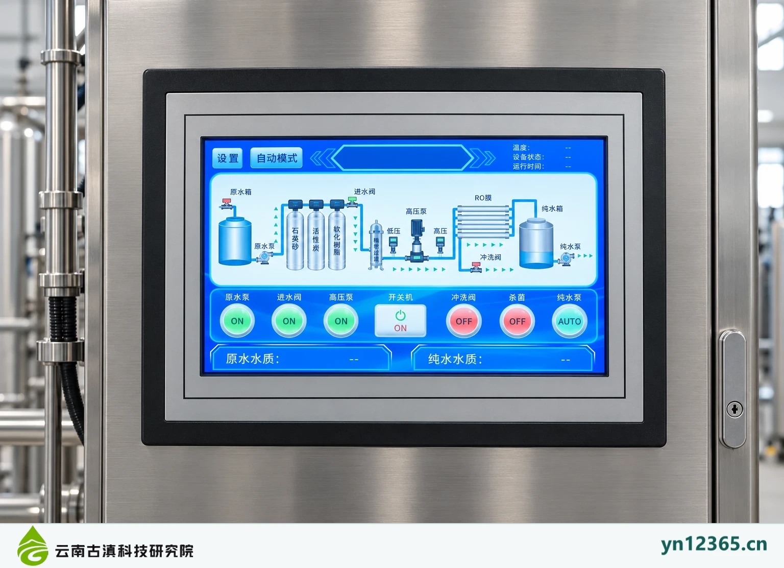
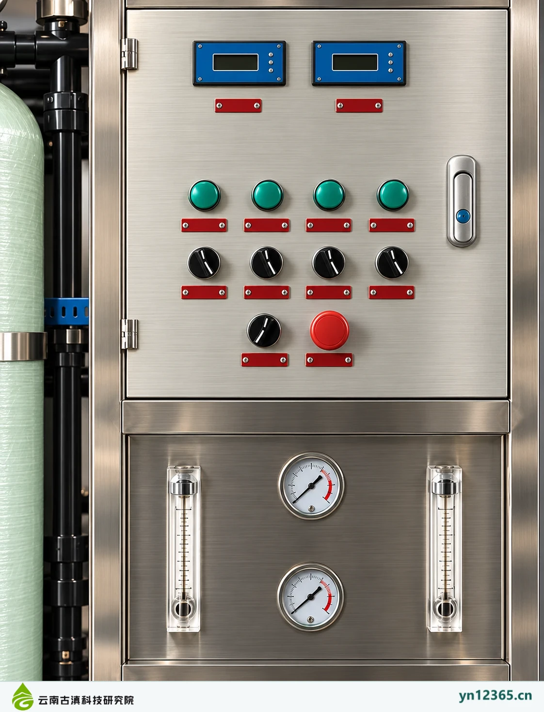
Displays, instrument arrays, and control panels help identify operating and recording points. Pictured numbers and buttons are illustrative, not measured records. Electrical drawings, programs, ranges, and functions require corresponding documentation.
Published · 2026-10-04Updated ·
Themed gallery: All images are AI-assisted illustrations, not actual customer project photographs.
Displays, instrument arrays, and control panels help identify operating and recording points. Pictured numbers and buttons are illustrative, not measured records. Electrical drawings, programs, ranges, and functions require corresponding documentation.
Read from overview to details
Compare relative equipment positions first, then examine connections, controls, or maintenance directions. Each image provides one discussion view. Unclear materials, models, functions, and readings must not be inferred as actual parameters.
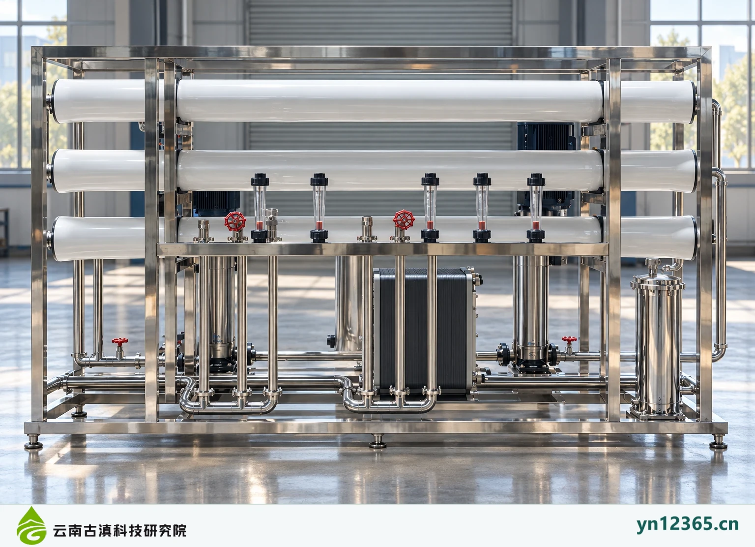
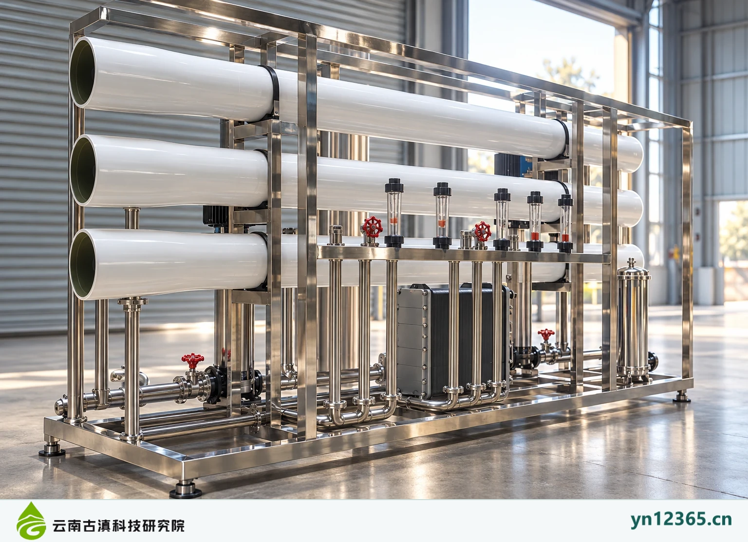
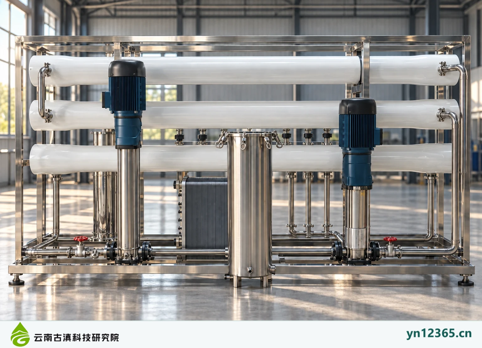
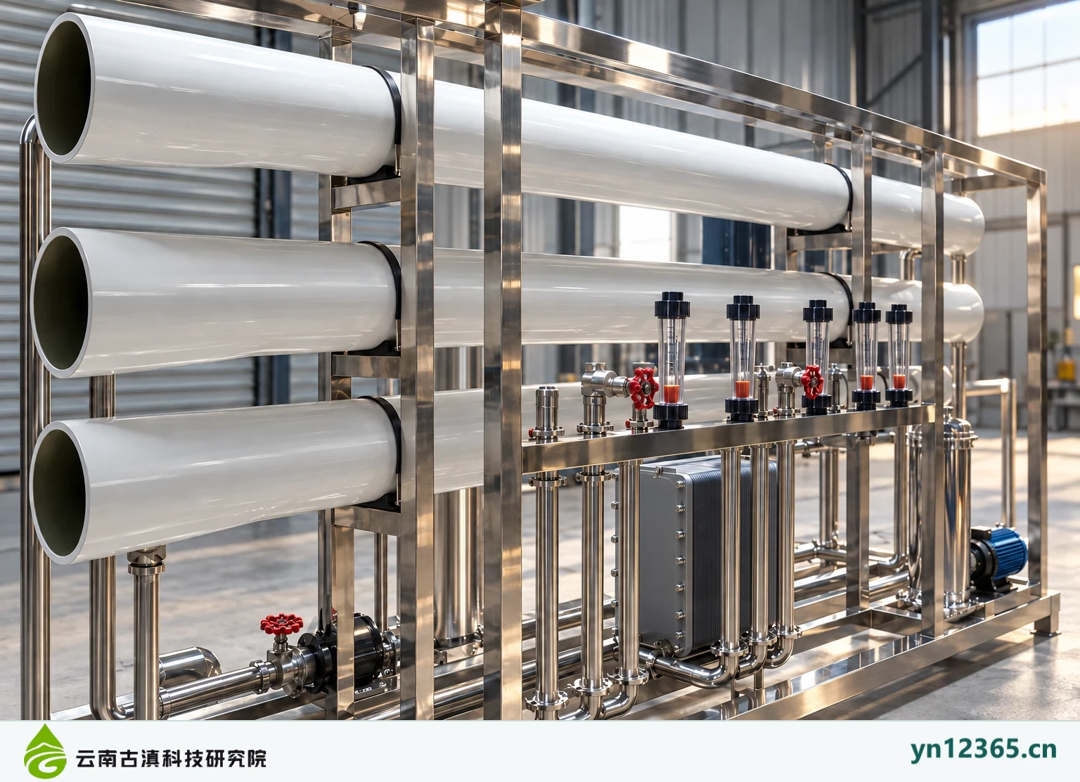
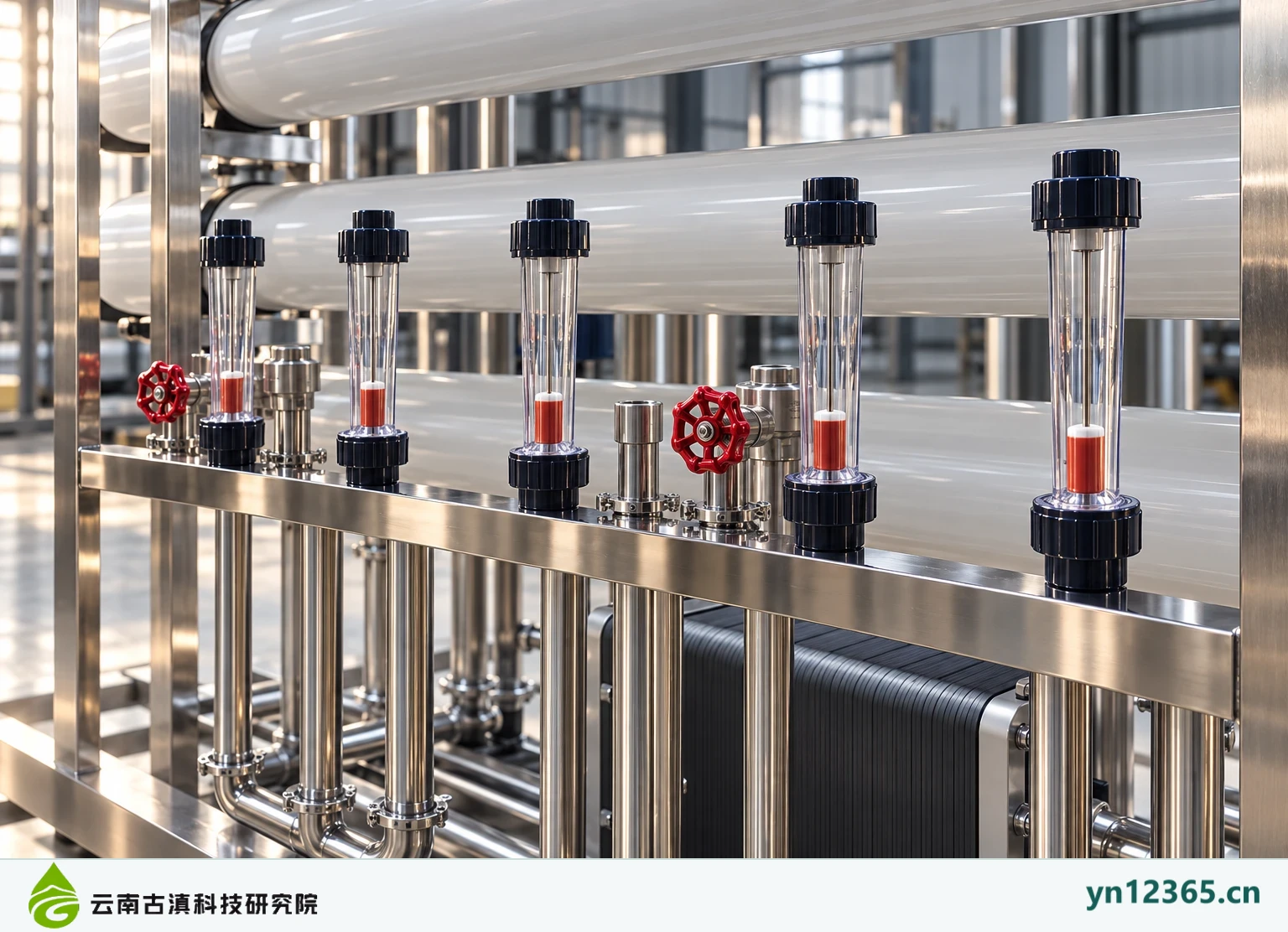
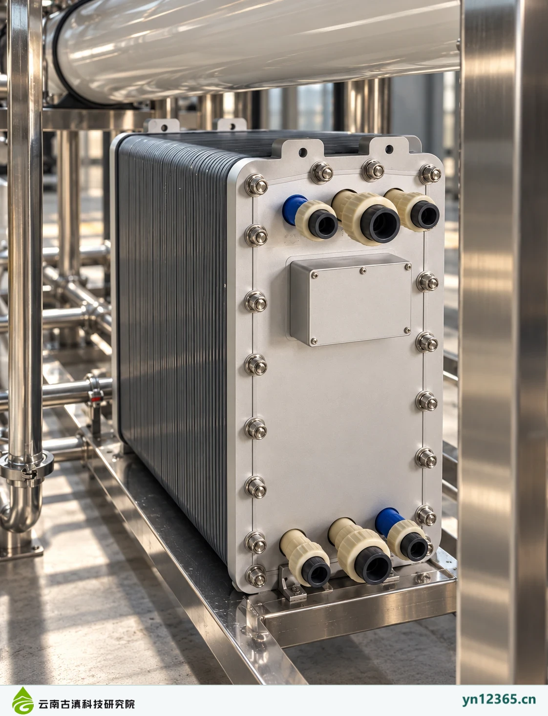
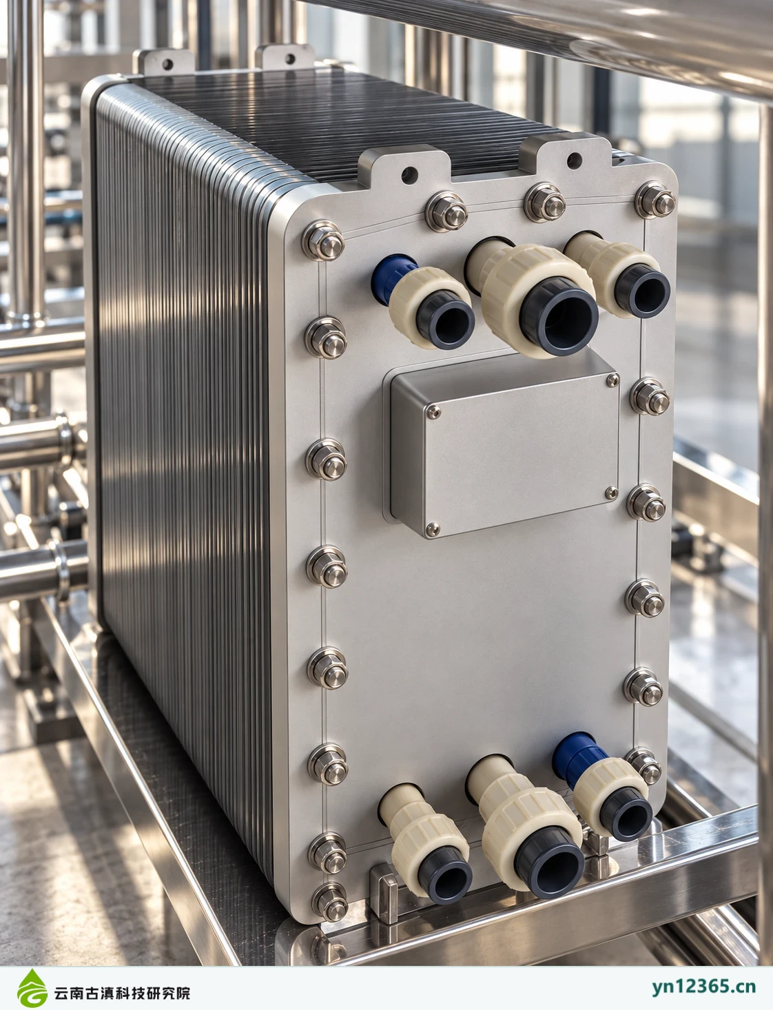
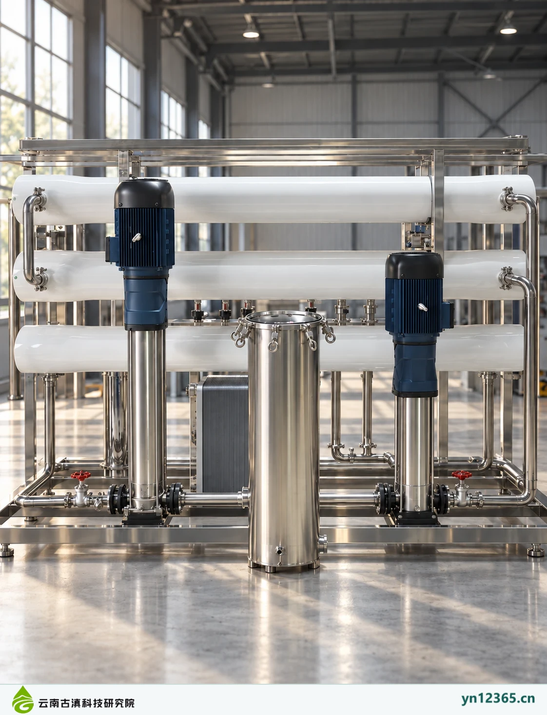
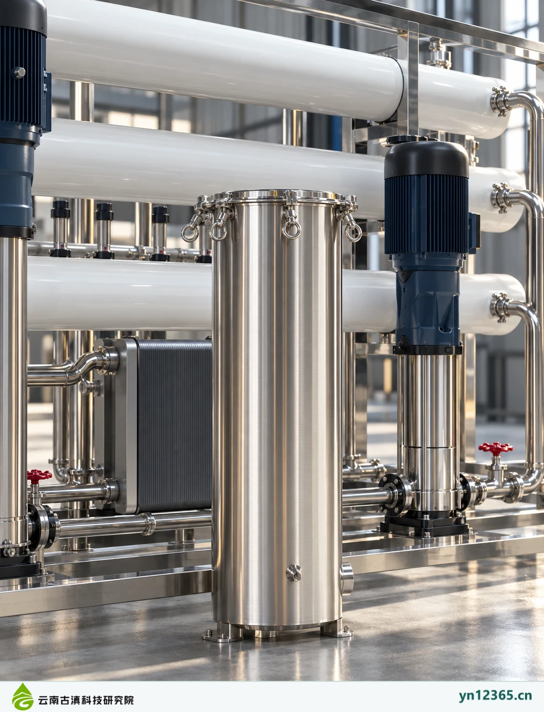
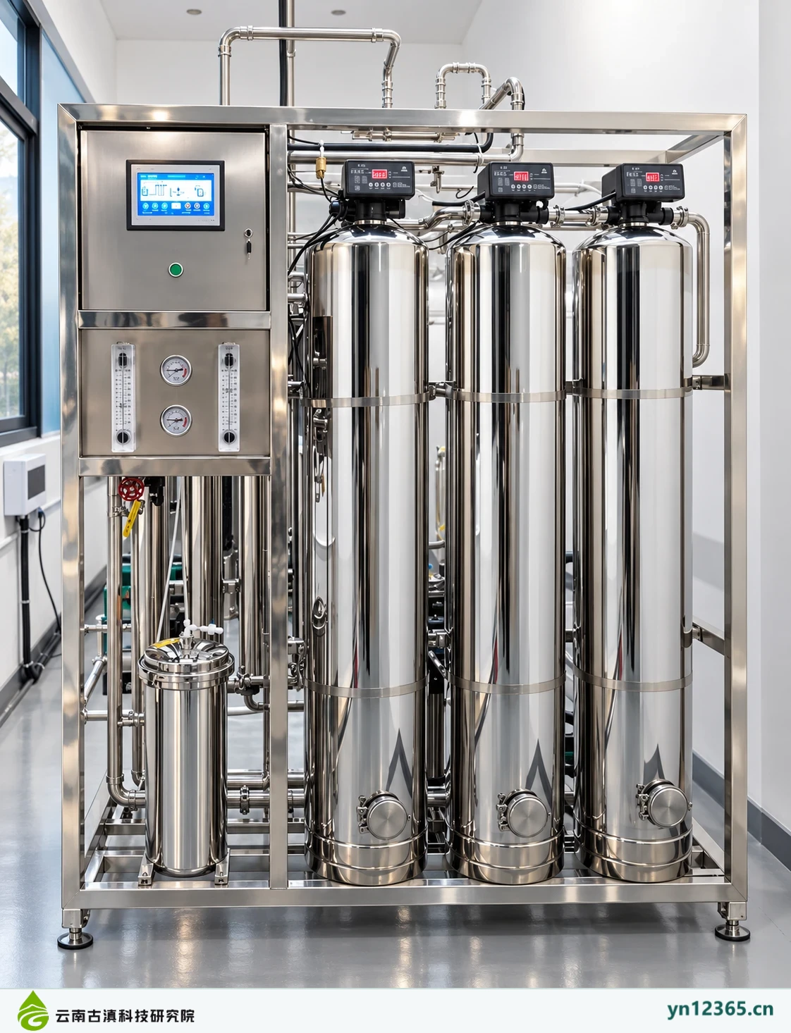
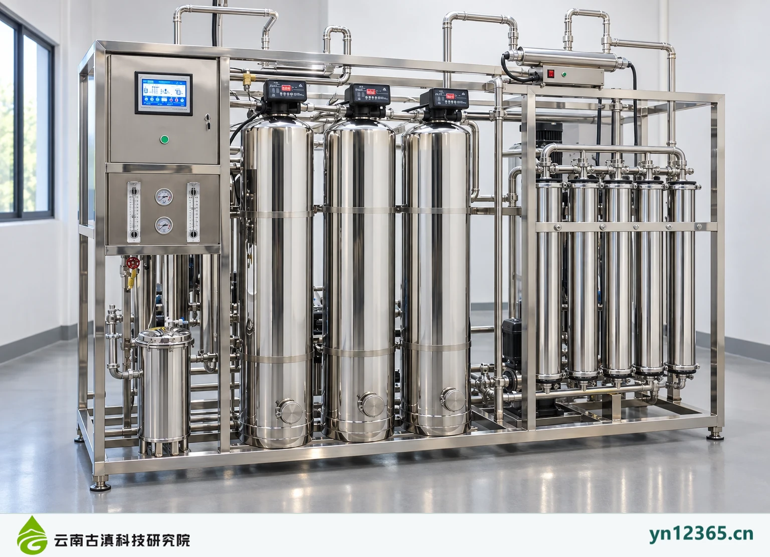
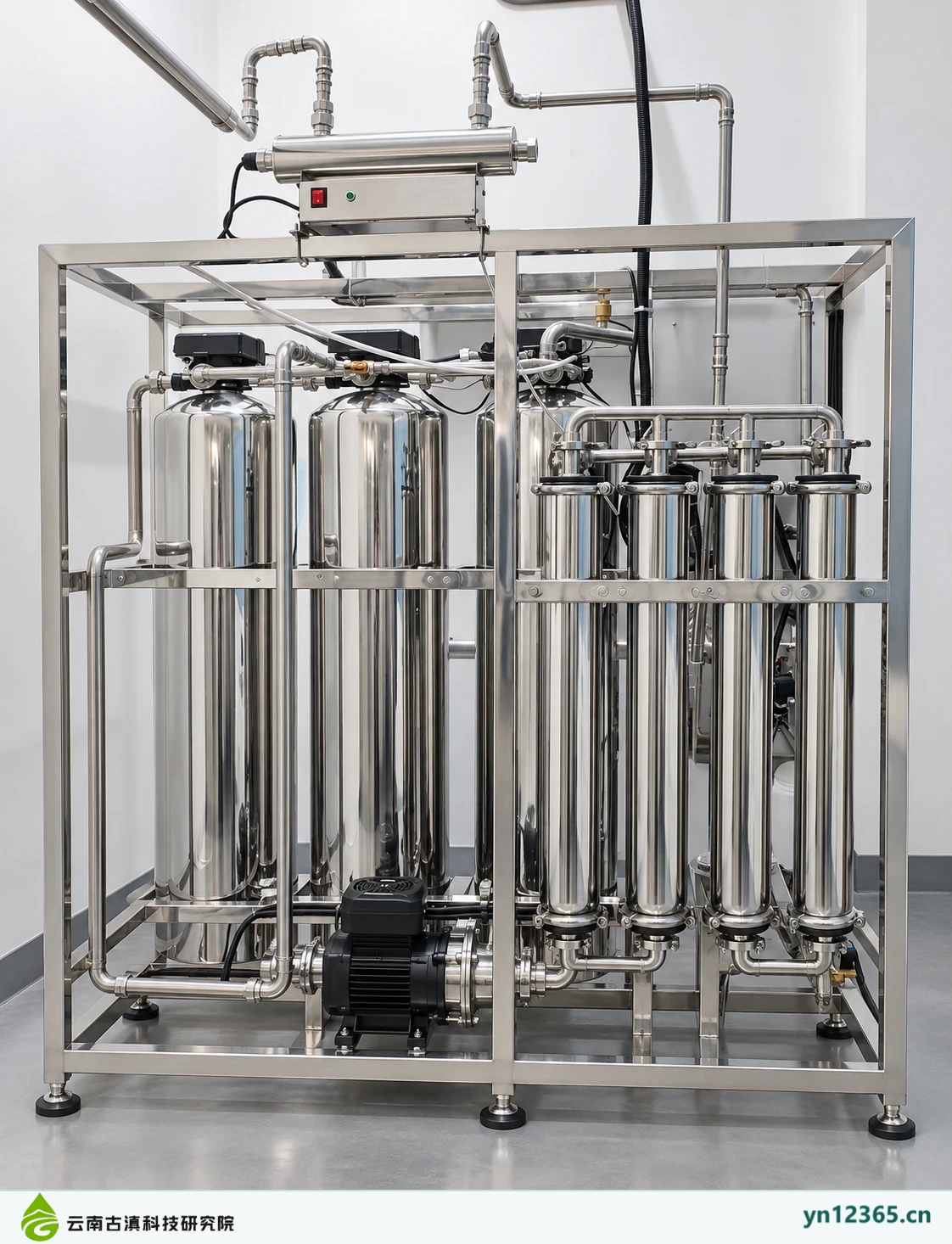
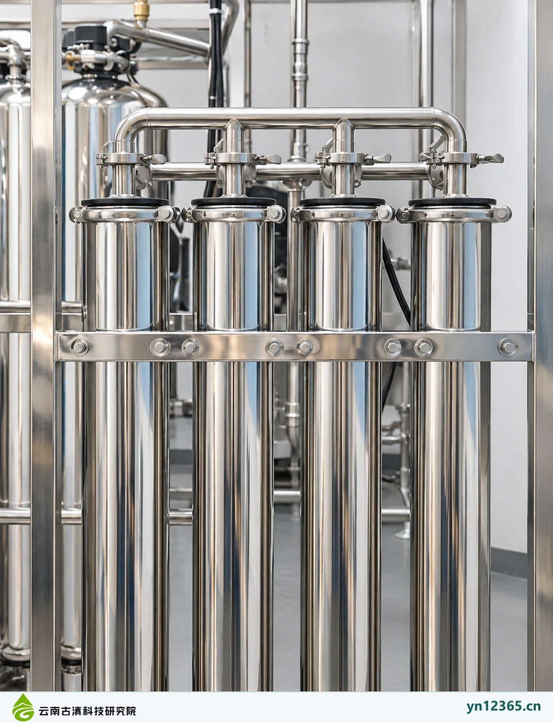
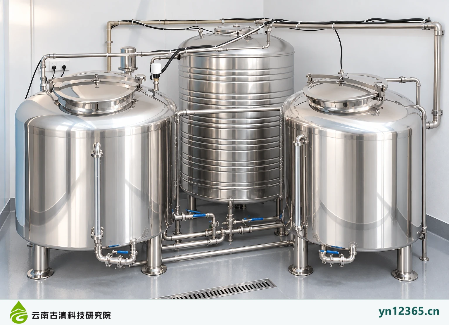
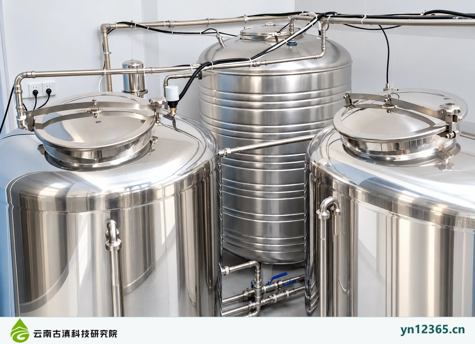
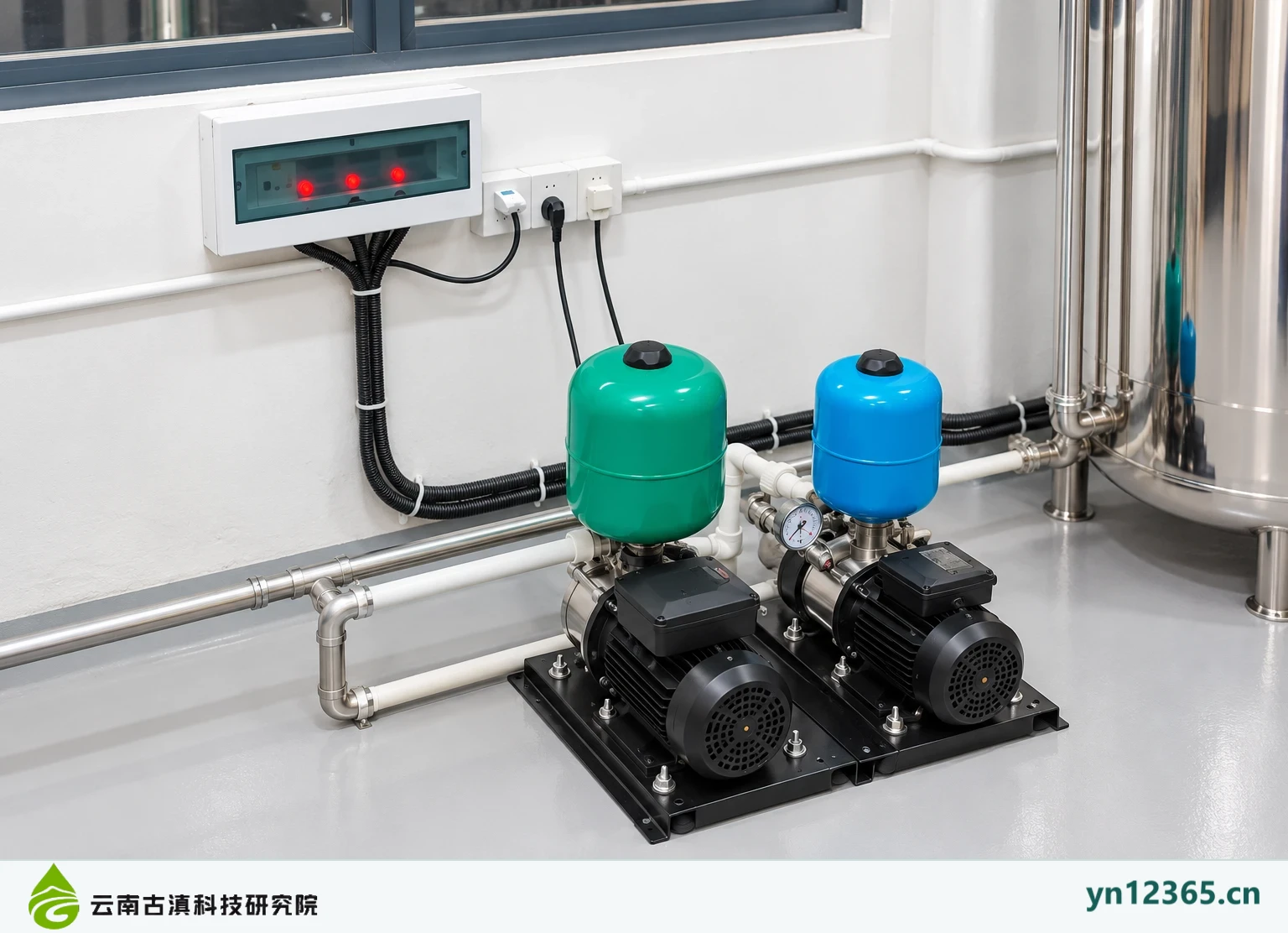
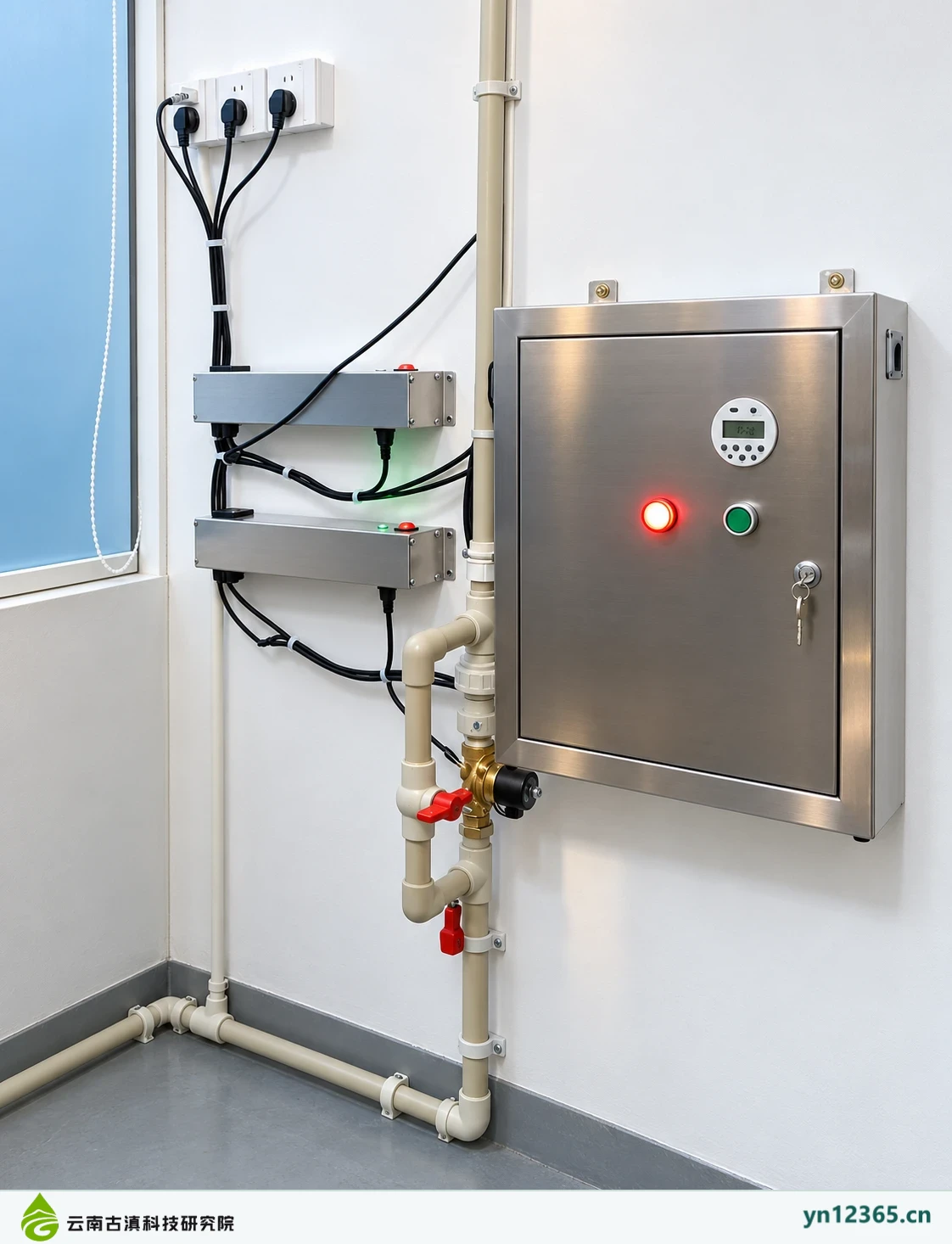
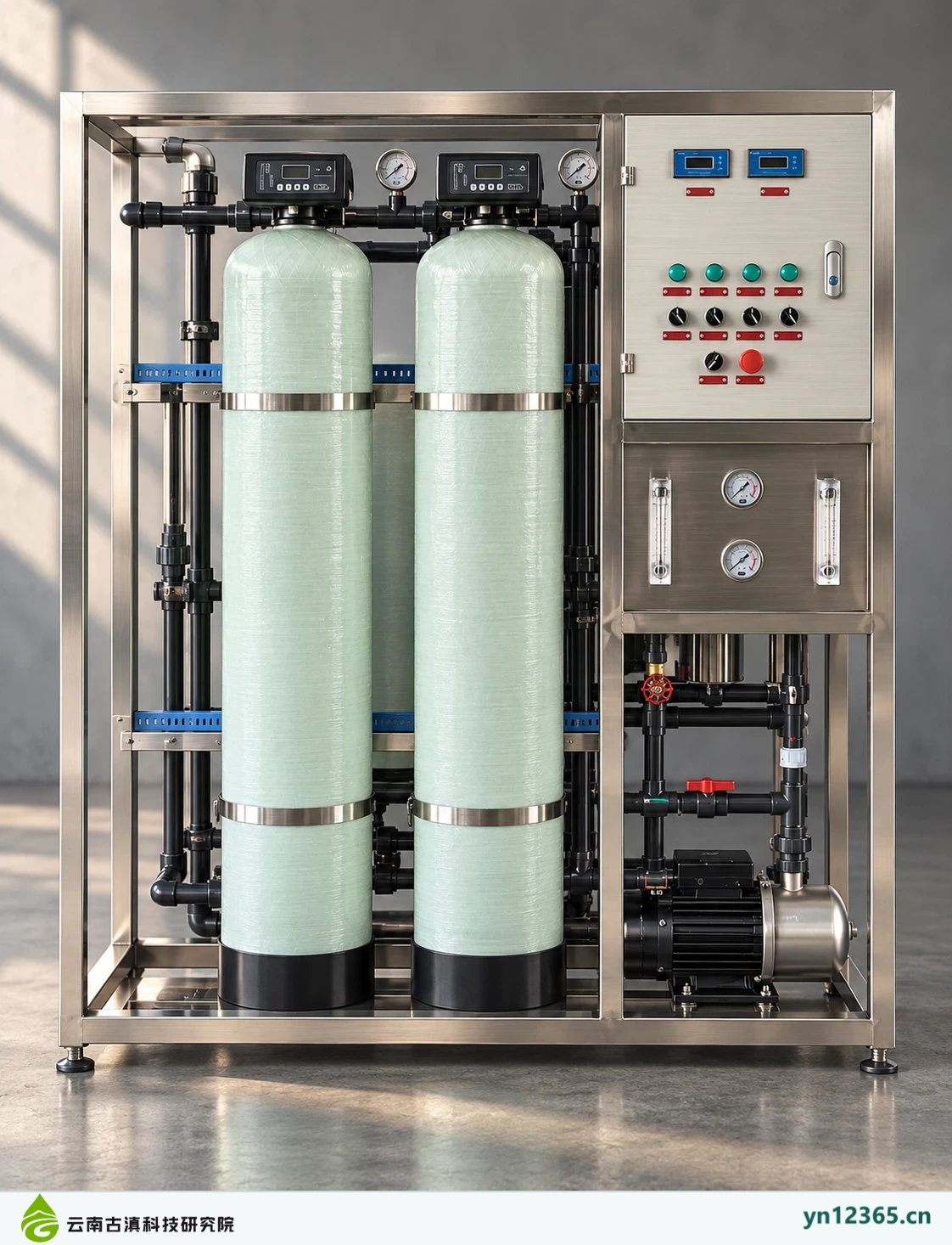
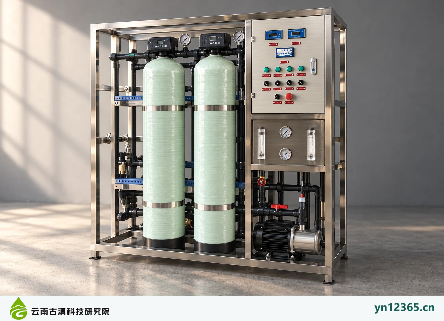
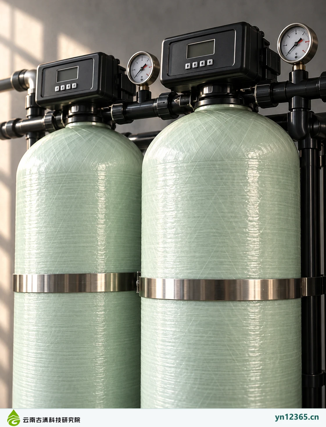
01_Front view: AI-assisted illustration, not a photograph of an actual model or customer project.02_Oblique view: AI-assisted illustration, not a photograph of an actual model or customer project.03_Pump-side view: AI-assisted illustration, not a photograph of an actual model or customer project.04_Membrane housing detail: AI-assisted illustration, not a photograph of an actual model or customer project.05_Flowmeter array: AI-assisted illustration, not a photograph of an actual model or customer project.06_EDI module: AI-assisted illustration, not a photograph of an actual model or customer project.07_EDI close-up: AI-assisted illustration, not a photograph of an actual model or customer project.08_Vertical pump set: AI-assisted illustration, not a photograph of an actual model or customer project.09_Filtration and pipework: AI-assisted illustration, not a photograph of an actual model or customer project.01_Front view of the complete three-tank equipment: AI-assisted illustration; not a photograph of an actual model or customer project.02_Angled side view of the complete three-tank equipment: AI-assisted illustration; not a photograph of an actual model or customer project.03_Control screen close-up: AI-assisted illustration; not a photograph of an actual model or customer project.04_Vertical membrane assembly: AI-assisted illustration; not a photograph of an actual model or customer project.05_Membrane assembly piping close-up: AI-assisted illustration; not a photograph of an actual model or customer project.06_Overview of storage tank group: AI-assisted illustration; not a photograph of an actual model or customer project.07_Storage tank lid details: AI-assisted illustration; not a photograph of an actual model or customer project.08_Twin-pump water supply assembly: AI-assisted illustration; not a photograph of an actual model or customer project.09_Disinfection control equipment: AI-assisted illustration; not a photograph of an actual model or customer project.01_Front view: AI-assisted illustration, not a photograph of an actual model or customer project.02_Oblique view: AI-assisted illustration, not a photograph of an actual model or customer project.03_Control panel close-up: AI-assisted illustration; not a photograph of an actual model or customer project.04_Two-tank filtration components: AI-assisted illustration; not a photograph of an actual model or customer project.
Turn observations into documentation questions
Check complete models, configurations, connections, and site requirements for the specific candidate equipment. Multiple images do not guarantee one supply configuration. Obtain corresponding operating documentation for repairs or modifications. Do not perform work directly from images.
Scope of this information:Compiled on 4 October 2026 from the available equipment-themed material. Equipment images are AI-assisted illustrations. This page presents possible configurations and is not evidence of a specific model, supply list, test approval, licence or completed project. The actual model, operating conditions and intended use must be confirmed against the relevant documentation. Prices, warranty and installation scope are subject to the written agreement for each order.